Rickenbacker M11 Jfet

classic Classic list List threaded Threaded
5 messages Options
Reply | Threaded
Open this post in threaded view
|

Rickenbacker M11 Jfet

vitt
Hi all!
I am trying to design a Rickenbacker M11 with 2N5457 jfets.
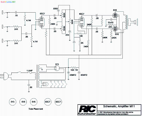
Following the schematic below i`ve took half of the 6SC7 double triodes, replaced 240k with 10k trimmers and set them all to have drain at 4.5v [noticed a more dynamic, less noisy sound].
What i am not undestanding is the connection between 10k resistor and the last 240k.
Am i doing right splitting the triodes? Because i am getting a nice clean sound out of it, but not the same distortion ive heard on youtube demos.


http://www.rickenbacker.com/pdfs/m11.pdf

Reply | Threaded
Open this post in threaded view
|

Re: Rickenbacker M11 Jfet

vitt
What I am not getting is the second triode. How come the 10k resistor looks connected to gate, source and even drain through a 240k resistor? To me looks like the 2nd portion of the first triode is "activated" only using the 2nd and 3rd inputs, and does not affects at all the circuit. But does the las triode change the tone in his way only if used all?
Schematic
Reply | Threaded
Open this post in threaded view
|

Re: Rickenbacker M11 Jfet

Travis
Administrator
The second tube (3rd and 4th triode) is a phase inverter.

This amp is a copy of the Fender 5C3

You aren’t going to get a FET adaptation to sound like that amp because it’s power tube distortion not preamp distortion
Reply | Threaded
Open this post in threaded view
|

Re: Rickenbacker M11 Jfet

vitt
Thanks for your reply! So I assume the first triode is the "preamp" section of it. Am I right?
Is only necessary have phase splitter, push pull to spot a power amplifier?
Reply | Threaded
Open this post in threaded view
|

Re: Rickenbacker M11 Jfet

Travis
Administrator
The phase splitter can be seen as part of the preamp as well, but you’re right it’s for the push pull power amp and is not needed in a pedal.

Typically when doing a JFET adaptation you will either copy the preamp up to the phase splitter or replace the phase splitter with a gain stage that approximates the gain of the phase splitter in the original amp

In this case if you do a typical JFET adaptation you are essentially left with a “fetzer valve” which is cool but not particularly reminiscent of the sound of the whole amp. For that reason you don’t see FET adaptations of the 5F1, 5F2A, 5E3, etc

There are pedals that try to emulate the sound of the complete amps which don’t follow the amp schematic like the Formula No 5. The Formula No 5 is probably the closest preixisting design to what you are trying to accomplish