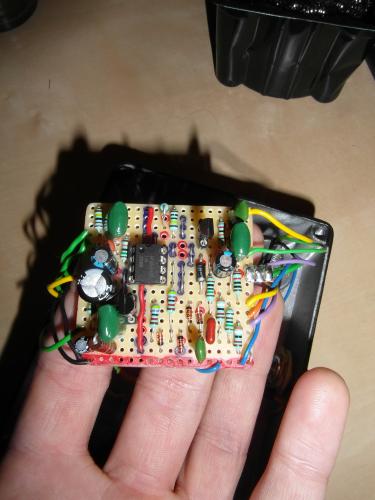
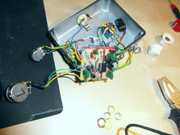
Roger Mayer - Voodo Bass O.D - FAULT BUILD
|
Hey guys
its the second time I am building this already... no luck Bypass - O.K when Effect is on I get absolutely nothing. I followed some of the comments done on the page. tried some of the suggestions there like replacing tone lug 1 and 3, replacing gain lug 3 to gain lug 1. still no luck. I read on the "Dummy COnnection" of tone 2 and output 3 - though I didn't try to simply connect the lugs to each other instead of connecting on the board... can not believe that is the problem. I never took voltage measurements if you could tell me how to do that with a multimeter I would be glad to! any leads would be mu appreciated! I cant seem to let go trying this one reading all those juicy comments I just got to get this time to life! thanks a lot |
|
Administrator
|
Herro. If you flip lugs 3 and 1 on a pot, it isn't going to fix anything, it will just reverse the direction of the pot's sweep.
It sounds likely that there is a wiring error. Could you post some pics showing your board and wiring? |
  I hope youcanunderstan what I did there.. Ill explain as well.. |
|
here are teh photos in high quality...
http://www.mediafire.com/view/z4dta60mrzt7j7g/SAM_2511.JPG http://www.mediafire.com/view/nppac86cchhh7x5/SAM_2509.JPG http://www.mediafire.com/view/6di5ok6fo9fy7lx/SAM_2518.JPG here you can really zoom in the photos as well.. I really dont se a off board wiring problem there.. any clues ? any one who bilt this exact one and ran into problems as well ? Im pretty sure I followed the layout really one to one.. I made sure I did not miss any cut or link (the double link as well) and I checked the non conductance between the cuts as well... thank you |
|
the red line was just an extra line I left for Ground connections. I often do that and it works fine so all teh jacks, stomp switch, ground to the board and ground from the dc plug are on that line as well
|
|
any ideas guys ???
|
|
In reply to this post by Tune Tone
Your Tone 1 is in the wrong row. I would think you'd still get output from it, though. So I doubt that is the only problem.
Did you correctly make the double link next to pin 4 of the IC? |
|
as I mentioned. I changed the position of Tone 1 and Tone 3 as it was said in the comments of the project by someone. I guess it should only change the directivity of the shaft.. no big deal and I tried it as well when Tone 1 and 3 were in their positions according to the layout.
the double link is correctly soldered as well... |
|
If you ever get no signal when the effect is engaged, there are two ways to debug:
* Measure your voltages. Do this for all amplifying components like transistors and ICs. * Make an audio probe. This will allow you to "listen" to the signal at various points and eventually isolate where the problem is. For example you may notice that the signal comes through at the output of an input buffer but is silent at the output of an IC gain stage. You can narrow down quickly where the problem is. If you want a quick operation that might help, try reflowing all of your solder joints. I have had "cold" solder joints in the past which resulted in this very problem (no signal at a critical junction in the circuit). And always check the obvious - e.g. your guitar is plugged into the input jack and NOT the output jack (don't ask me how I know this...  ) )
|
|
This post was updated on .
In reply to this post by Tune Tone
I'm not talking about reversing the lugs. I'm saying that the current position of Tone1 is in the 11th row, when it should be in the 10th row. Did you make any substitutions? Are you using a LM308 for the op-amp and BC549's for the transistors? |
|
did you notice the extra line I marked in red ? I added this for grounding connections
|
|
Yes I noticed it. I'm counting from the top. Your Tone 1 is right next to your +9V. There should be a row separating them.
|
|
you are right... I will definatily have it fixed later when Im home. Though as you said.. can it solve the problem ?
I would measure voltage though Im not sure how... how do I do that with a multi-meter ? thanks a lot for your time and support btw !!! |
|
Your welcome. I doubt it will do much more than change the operation of the Tone control, but you never know.
And, yes, voltages are the way to go now. It's pretty easy. Set your meter to DC voltage (if you have different ranges, choose something slightly larger than 9V). Put one probe on the ground pin of your voltage supply, and the other on the 9V pin. If you get a negative reading, reverse the probes. Then write down your reading. Take note of which probe is on ground. That one will be your 'ground probe'. Put the ground probe on the ground lug of your input jack (you can hold it there with alligator clips if you like) and touch the other probe to each pin of the IC, and each pin of the transistors. Write down what you measure and post it here. The for IC's is counterclockwise numbering, starting at the top left pin. It looks like this: 1 8 2 7 3 6 4 5 In most cases (including this one) you can tell which one is pin1 because there will be a semi-circular notch between pin 1 and the last pin (pin 8 in this case). Occasionally you'll get an IC without a notch, but it's unusual. By the way, did you make any substitutions. Are you using an LM308 and two BC549's? |
|
By the way, you should do these measurements with the circuit powered up.
|
|
thanks!
Im gonna buy parts to build an audio probe. what I dont get at the moment why in this tutorial for example the author is telling to get a 1/4 inch female jack ?? if this goes to an amp, why should I not use a jack to plug it straight to the input of an amp OR at least a normal jack input like used for enclousers so I can plug it to a cable that goes to an amp ? http://www.guitarpcb.com/apps/forums/topics/show/7219163-how-to-build-an-audio-probe-photo-essay |
|
Voltage measurements:
IC: 1: 0 2: 0.01 3: 0 4: 0 5: 0 6: 0 7: 0.01 8: 0 D1: A:0 C: 0.02 D2: A: 0.01 C: 0 D3: A: 0.02 C: 0 D4: A: 0 C: 0.02 D5: A & C: 0.02 Q1 (top) C: 0.01 B & E: 0 I guess something is wrong .. ? and yes I used a LM 308(N) and 2 BC549 The voltage mesurement after the 150R resistor is 0. Could it be that this resistor is faulty ? it's mesurement shows its 148.8 R.. so I guess its ok |
«
Return to Open Chat
|
1 view|%1 views
| Free forum by Nabble | Edit this page |

