Roland Double Beat fuzz section
12


12
Re: Roland Double Beat fuzz section
|
Oh. I forgot to mention that I raised the value of the gate pot to 500k.
That gave me more range and gating (but also provoked the need for the booster at the input) Neil |
Re: Roland Double Beat fuzz section
|
In reply to this post by Neil mcNasty
For those of you who don't like the extreme amount of noise in this pedal (I do, he,he...), you could raise the two 22k resistors going from q1&2 emitter to ground to about 82-100k.
This will reduce the gain a bit (which is the reason for the noise), but you'll still have a very nice sounding fuzz. After doing this you will also get a lot more response from the fuzz knob as you can lower the gain a bit more. This also has an effect on my suggested gate/pinch mod as it no longer will become totally gated, but will function more as a loose/compressed adjustment. Sounds very nice in my ears. I have decided to use a 4pdt stompswitch to switch between the two different values, so that I can make the pedal go apeshit when I want it to. There is still a bit of noise after this mod (reminds me of ground hum), but if you give me a litte more time I hope that I will figure out a way to deal with that issue too. Complete layout with all my mods coming soon... Boy am I having fun with this!  Neil |
|
You might also want to try upping that filter cap between 9v and ground, 10uf seems a little low to me, 100uf might do a better job of removing any power supply noise.
Cheers Dave |
|
In reply to this post by Neil mcNasty
just built this one today. Thanks for posting it Fredrik!
for those that like the component values right on the vero and the transistor EBC designations, I redrew Fredrik's vero to build mine. here's what it looks like: 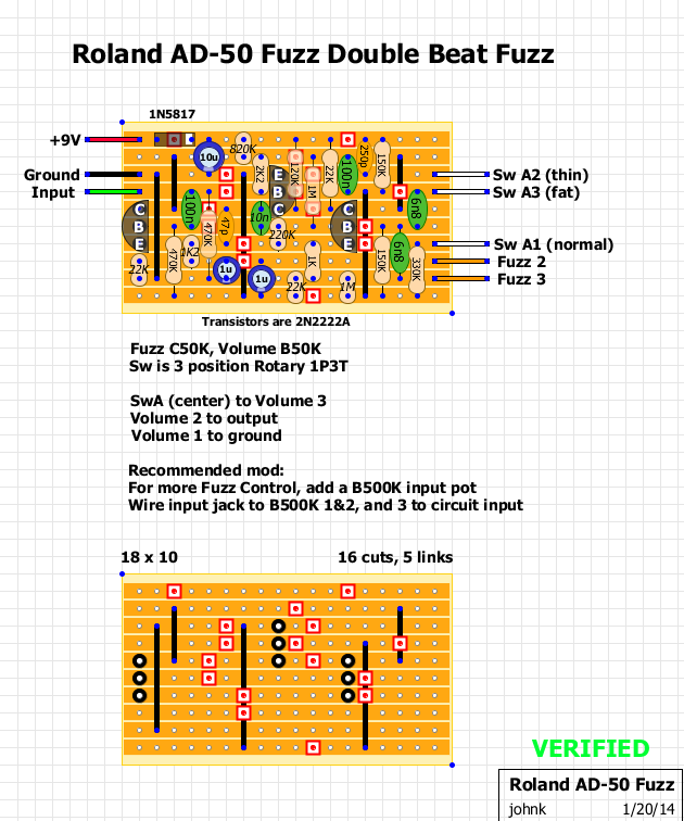 I also added the input mod so you can 'tame' the fuzz or run it full up. |
|
In reply to this post by Freppo
I finally built one of these over the weekend using Freppo's layout. I also incorporated the gate mod as suggested above. It is an amazing fuzz, it is just soooo huge sounding. My suggestions for improvements are to use a c50k pot for fuzz as it gives a more sensible taper, and also to play with the resistor values for each of the different modes as there are quite large volume changes between them.
Thanks for the layout Freppo, definitely should be added to the main site. Cheers Dave |
Re: Roland Double Beat fuzz section
|
Here is my super-modified version of the Double Beat, that I have named "Huzzle & Cuzz Fuzz".
I guess that I have now spent more time on this circuit than what both JHS and Lovepedal has spent on all their pedals combined, so I really should be able to call this my own design. Anyway, I will be making a few of these, since the response from my friends has been amazing, and many people are asking me about making super compressed over the top fuzzes these days. And I'm also thinking about getting a proper PCB made for it as well, if the interest keeps up/growing. Here you go: 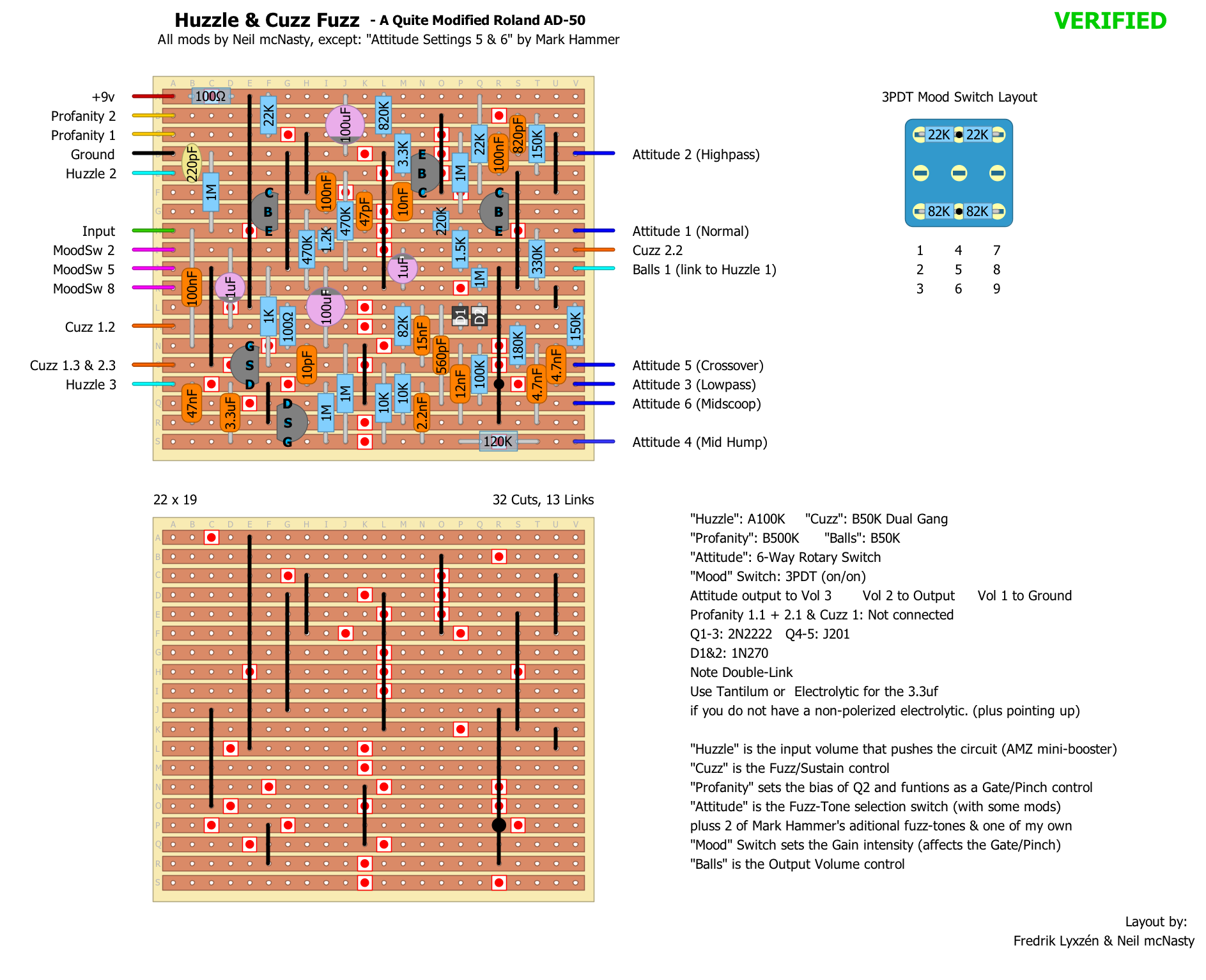 This is what I did: - Adjusted some of the tone settings, and added 2 of Mark Hammers extra Tone Settings + made one of my own (the 4th, which is a mid hump setting). So now it is a total of 6 different Tone Settings. - Added a dual gang pot for the Fuzz control, so that I was able to adjust the gain of Q1 as well, enabling me to actually get some "normal" amount of fuzz out of it as well. - Added "Gate/pinch" control, which is actually just a sag/bias control for Q2. - Added a 4PDT switch with 2 different resistors to ground on Q1&2, to enable even wider range of compression/pinch/gate modes. - Inserted a AMZ Mini-Booster at the front, to push the gate harder, and also push the fuzz so hard that it implodes. - Changed a few values to remove (a tiny bit of the) harsh attack. - Added 220pf cap at Q1 to roll off some high end harshness. BEWARE! This has become a monster and is not for the feeble minded! Enjoy! |
|
Wow! Nice work Neil

check out my building blog at www.parasitstudio.se
|
|
In reply to this post by Neil mcNasty
I also like this fuzz a lot. Standard layout without the thin setting. But when fuzz is full on it indeed gives a lot of feedback that can be difficult to control. Is there a setting with the gate where feedback is reduced but the sustain is still optimal ?
|
|
In reply to this post by Neil mcNasty
have already built one of these which i'm very fond of. am looking at potential tweaks since i'm having a reboxing phase and now is the opportunity to add extra pots and switches.
have been considering mark hammers three additional tone options (two of which neil uses above) which mark schematises (new word) here: original post: http://www.guitarscanada.com/showthread.php?53902-Roland-Double-Beat 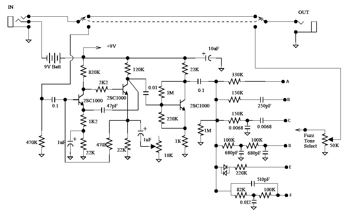 as i have a build i'm happy with anyway i am basically considering adding a vero tone stack daughterboard with the full six hammer settings on and just patching it in to the original circuit. has anyone here tried the non-standard hammer options, or anything else interesting, re extra tone options for this one? hope to be able to try these out on the breadboard soon but thought i would canvass opinion here ahead of that in case anyone has any wild and wonderful ideas. btw nice looking build neil. if i hadn't a perfect standard version built already i'd would go for it. |
|
Still one of my top 5 fuzzes I've built. As I mentioned earlier in the thread, adding a pot at the input really opens up a whole new range of fuzz tones to be had. Really nice OD low gain stuff.
|
am in total agreement re the addition of the 500k input pot. it's a must-have. |
|
In reply to this post by Kinski
A Treb/Mid/Bass tone stack would be pretty cool with this fuzz I bet.
|
|
In reply to this post by Freppo
Just built this using Johnk's layout without the Input pot and am liking it a lot , great fuzz. Think i am still going to add the input pot though as it sounds, reading the comments, that its the best option. Cheers guys for the thread and awesome layouts.
"Red velvet lines the black box"
|
|
This post was updated on .
In reply to this post by tabbycat
in my brain this vero can be patched into an existing ad-50 build to allow you to add the six tone options as propsed by mark hammer in the schematic and link posted above.
in reality things may be quite different. 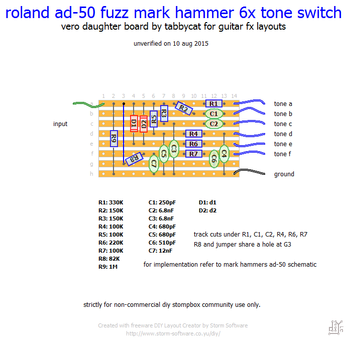 the idea is that this is a daughter board that sits between the 100n on the main ad-50 board and the volume pot, to replace the three tone options available on the stadrad board with the six proposed by mark (three are the standard ad-50 tone options, the other three are experimental and extra-curricluar for-kicks options, including a diode clipping option). if you are using johnk or fredrik's layout, take a wire from the bottom right hand corner of that board (there is a spare hole right at the end under the wire marked fuzz 3) to the daughter board (via input wire), then take the six tone wires that exit from that to a six position rotary switch (a,b,c,d,e,f). then take the centre pole of the six position switch to the volume pot (se mark's schematic). don't forget to ground the daughter board to the main board. obviously you do not need to wire up any of the three tone wires on the original board. these are replaced by the first three options on the daughterboard. basically this is for those who already have an ad-50 build they are happy with (and who wouldn't be, it's sex in a box) but who want to try a few more tone options. mark hammer is a guru so i thought his ideas would be a solid place to start. if you find any of the options don't suit you, try swapping the resistor and cap values for the tone that doesn't please you. similarly, socket the diodes and play around with what you've got. the daughter board is pretty small so should fit somehere in a 1590b alongside the main vero. obviously this hangs on whether the vero layout is any good, so would it be possible for a member out there with black belt grand master vero skills to give this a quick scan? thanks if poss. |
|
Hello,
Another layout has been published on this site : https://dirtboxlayouts.blogspot.com/2020/10/roland-ad-50-double-beat-w-mods-by-mark.html I built it, it works and sounds great, but i am experiencing a volume issue which is beyond my skills : the output signal is much below unity gain. When i am audio probing the circuit, I hear a very loud signal around Q3 (which let me think that the circuit work as expected, until a certain point where there is some noticeable volume drop). Would anyone have any suggestion why i am getting such a volume loss? I post a picture of my veroboard's back, below the layout... 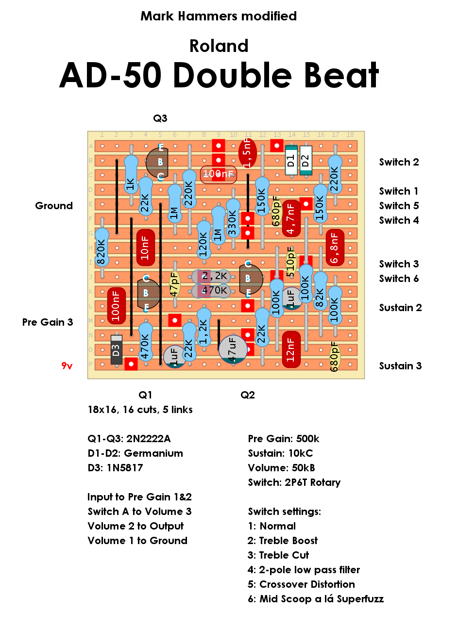 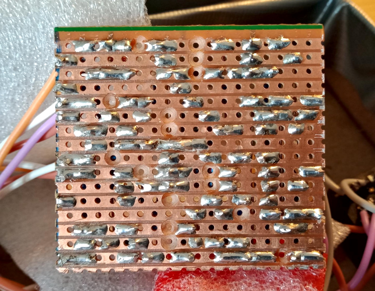
|
|
I think the circuit works fine, but the output doesn't go up to unity gain, so i added a LPB daughterboard, and it does the trick nicely :)
|
|
In my build the output is very loud
|
|
Yes, this is what i have read a couple times, but here I had a very noticeable volume drop. I have put a Linear Power Booster daughterboard after the main board, and it works fine now.
|
Re: Roland Double Beat fuzz section
|
I know it has been a while and you got this working, but that solder point 5 rows down and 7 from the left looks like it could be the culprit.
|
«
Return to Booster, OD, Fuzz, Distortion
|
1 view|%1 views
| Free forum by Nabble | Edit this page |

