Hey guys!
I have built the Rusty Box bass preamp pedal from
http://tagboardeffects.blogspot.com/2014/03/tronographic-rusty-box.htmlEdit: The pedal is a recreation of the Traynor TS50B Preamp section. Here is the schematic
https://schematicheaven.net/bargainbin/traynor_bass_ts50B.pdfUnfortunately it does not work as it should and I don't know where to look for mistakes anymore.
Let's go over what is audible first:The pedal does pass sound, but it's a whole lot lower than the input volume. The Volume and gain knob do generally work, the lo/hi switch does work and the boost also works. Considering the treble/bass middle pots I'm not entirely sure because I only checked the Audio signal with a small "workshop amp". As far as I can tell the treble and bass pots do nothing or very little to the signal, the middle pot does affect the signal.
Now to the voltages:The power supply itself supplies the proper voltages. I did not write them down before connecting it to the main board but they were fine.
On the left are voltages someone measured on a working unit, on the right are mine
Voltage Rails
+17.3 +16,3
-16.8 -13,9
Tl071
1.-16.7 -13,6
2. 0 0
3. 0 0
4.-17.8 -13,7
5.-16.7 -13,6
6. 0 0
7. 17.4 16,5
8. 0 0
Q1 - BF256B
D. 0 0
S. 0 0
G.-15.9 -13,6
Q2 - MPSA18
C. 18.1 16,5
B. -1.7 8,6
E. -3.7 8
Q3
C. -7.4 -9,3
B. 0 -2
E. 0.6 -5,8
Q4
C.-5.9 -9,3
B. 0 -2
E. 0.6 -5,8
Q5
C.-17.6 -13,3
B. 0 -6,4
E. 0.6 -5,8
Q6
C.-17.6 -13,8
B. 0 -6,8
E. 0.6 -5,4
Q7
C.-7.1 -9,3
B. 0 -2
E. 0.6 -5,8
Q8
C.-17.6 -13,8
B. 0 -6,4
E. 0.6 -5,8
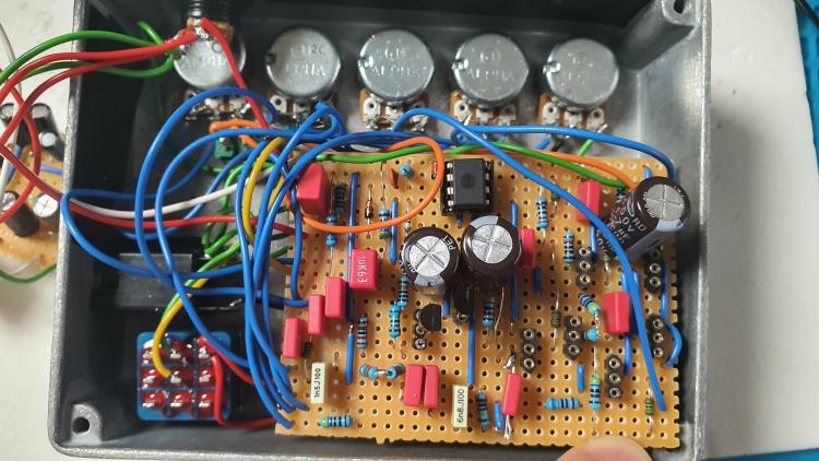
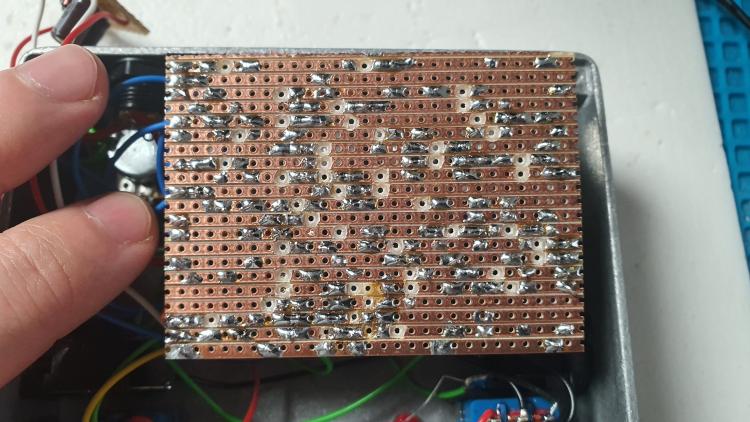
Here are photos of the circuit board:This was my first vero board pedal so I did all the drilling on the solder side and then noticed, that I had to reverse the layout on the component side. One picture shows the solder connections, and holes drilled in the orientation shown on the blogpost, the other picture is the board flipped vertically. The IC is the correct one, but because of the flippped layout I had to flip the ic on its back as well. I removed Q3-Q8 for better visibility. And yes - those 4.7uf caps are way huge but smaller ones were not in stock at the time ;)
I double and triple checked every jumped cable, drilled hole and placed component, made sure as good as I could, that no connections are bridged. I'm relatively sure that ther is only one really dumb mistake
but I wasn't able to find it so far.
Any hint would be much appreciated!

