SSL Variable Harmonic Drive - Anything Like This Available?
|
Hi Folks,
I work in audio post and have a small home studio where I do mixing and the like. I'm interested in making some sort of mild saturation/distortion device that I can use when recording or for "treating" existing recordings. There are a few commercial products available that do this sort of thing - Silver Bullet, Neve, etc. One that I'm interested in is made by SSL and is called Variable Harmonic Drive. It's available across their hardware including 500-series units which makes me think that it's not something particularly complicated. There's some info about it here: https://www.solidstatelogic.com/products/vhd-pre-module As it's a commercial product there's no info available anywhere about how it works or what it is. Because it's a distortion device I'm hoping that someone here might be able to help out with ideas about how it works or even whether there is something in the realm of guitar FX that would do a similar job? Any thoughts or suggestions welcome. Cheers, Chris |
Re: SSL Variable Harmonic Drive - Anything Like This Available?
|
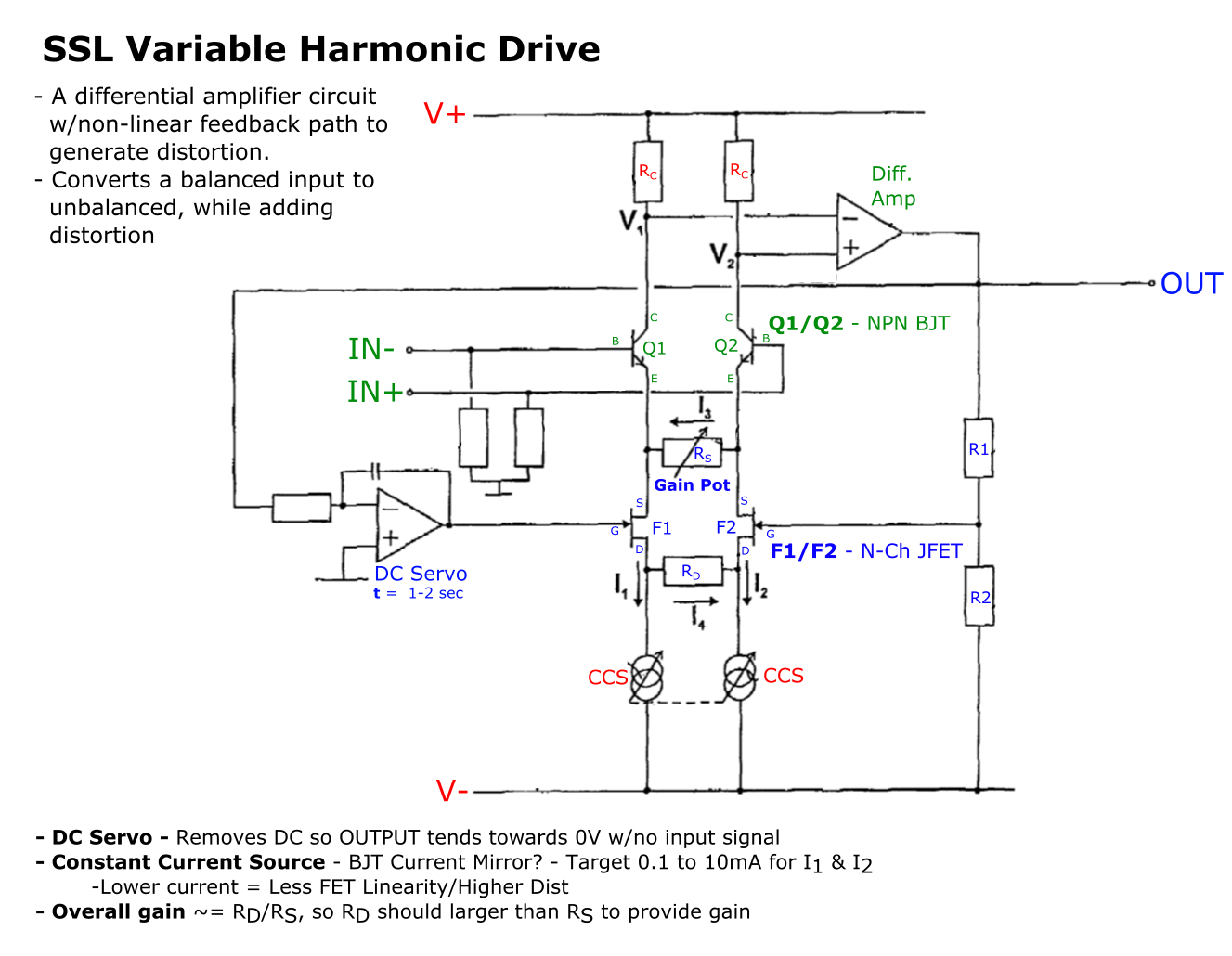
There is a GroupDIY thread where someone requested the patent number, but the patent is pretty hard to track with all of the number labels, so I edited in the functions of each block instead:
 A basic summary of the patent text: 1. Initially I1 & I2 are equal. 2. As differential signal applied to circuit input, the voltage difference at V1 & V2 (voltages across diff amp inputs) will cause diff amp to produce negative feedback in order to make these voltage equal. 3. Differential input voltages at BJT base result in modifications to each transistors emitter current - EX: For diff voltage, Q1 emitter current may increase, while Q2 emitter current decreases. 4. In the above case, current I3 will shunt between emitters of Q1 & Q2, through Rs 5. As shunting of current starts to take place (I3), the feedback loop will attempt to rebalance the circuit. Feedback signal is applied to gate of F1 & F2. As negative feedback, the current from the Drain of F1 will increase, while current from Drain of F2 will decrease, resulting in shunting of current I4 through resistor Rd. 6. Due to the non-linear characteristics of FETs, the flow of current I4 will not behave in the same way as the flow of current I3, such that the feedback characteristics are distorted with respect to the input signal thereby ensuring that the distorted characteristic is imposed up circuit output in a controllable fashion 7. Constant current sources are made variable such that a reduction in the level of current flowing through the FETs increases the non-linear characteristics Overall gain is related to the ration of the resistance of Rd/Rs: - Resistance of Rd is made larger than Rs to provide gain - Rs acts as a gain control as it's a variable resistor Unfortunately, I don't see any easy way to adapt this for an unbalanced input like a guitar pedal, but maybe someone else has an idea. |
Re: SSL Variable Harmonic Drive - Anything Like This Available?
|
Couldn't you just use a line driver circuit in front of this? That might be interesting.
Through all the worry and pain we move on
|
«
Return to Open Chat
|
1 view|%1 views
| Free forum by Nabble | Edit this page |

