STM Speaker Saturation Simulator SMD/TH hybrid


|
This Speaker Saturation Simulator is an overdrive that provides soft clipping via diodes to ground. There are other ways to get soft clipping that will sound very similar, but this is an interesting circuit. It was designed in 2004 by Sebastian from Runoffgroove (though I don't think it's on the runoffgroove page. I found it on DIYSB), but it was based very closely on the tape saturation simulator by LXH2. The schematics for the tape saturation simulator and speaker saturation simulators are nearly identical, except the tape sat has an additional amplifier stage after the diodes, plus an output buffer that seems kind of redundant. I wouldn't expect it to sound much different, but I haven't built the tape saturation simulator.
Neither of these circuits is physically modeled after either tape or speaker saturation. They're just diode clippers with a twist. The idea behind both designs is that you stack four pairs of germanium diodes on top of a pair of silicon diodes to get soft clipping. Since Ge has a soft knee, the knee of 4 of them in series will be even softer, but the forward voltage will also add up. So you have to boost the input to an amplitude of about 2V before you'll get any clipping, then you'll have to drop it back down with the volume control unless you're looking for a serious boost. The thing is, though, even silicon diodes will give soft clipping if there's a resistor (AKA 'saturation pot') between the signal path and the clipping diodes. So you could probably build something that sounds identical with just the two Si diodes, you'd just have to play with the saturation pot value until it sounds right. It's designed to be used in conjunction with a speaker simulator, to add distortion similar to speaker compression. But like I said, it's an overdrive. Use it however you want. I made some mods to this one. Read on after the pictures if you want to see my breadboarding notes, which include my mods and descriptions of how the circuit functions. I stood up the diodes to keep it small. Sorry if that bugs anybody. I've breadboarded the circuit, and built the vero, but I haven't tested the built vero yet, so technically it's still unverified. Layout: 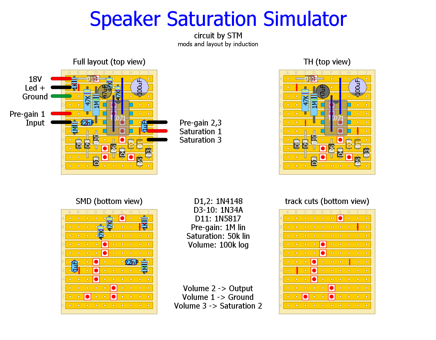 Schematic with mods: 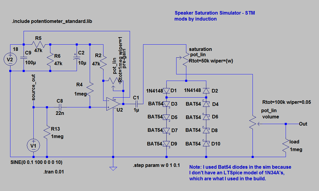 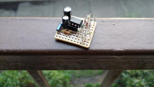 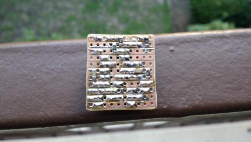 Breadboarding notes: - Stock circuit gives good compression at 1V input, but almost no compression for 100mV input. - Good idea to have control over input gain. - STM schematic has compression decreasing as saturation pot is increased. Reversing the pot makes saturation increase with setting, but volume decreases with setting. - Maximum compression scales with saturation pot value. - The circuit functions like a compressor with a fixed threshold (diode cumulative Vf), ratio control (saturation pot), instantaneous-ish attack and release, and makeup gain (the output volume pot works like makeup gain because the gain stage gets the output above unity). - A pregain pot would provide the same flexibility as a variable threshold. Mods: - Replace 47k feedback resistor with 1M pot for variable input gain (allows the same compression ratio and output volume for 100 mV signals as for 1V signals). - Increase saturation pot to 50k for increased maximum compression. - Remove R1 for wider output range (decrease the minimum output volume). This thing may be kind of finicky to use as there all three pots control volume (very interactive). But it's redesigned so that smaller input signals can still be compressed (boost input signal, compress, reduce volume at output pot for unity gain, or leave it high for boost). You should be able to get a similar output signal for any reasonable volume of input signal. This also allows the circuit to work on guitar level signals, as well as on line level signals. Strategy: dial in compression with pre-gain and saturation pots, A/B with bypass signal to hear the effect and to set unity volume with output volume pot. Note: Changing any amp or pedal settings that affect the volume will also affect the Speaker Sat operation (realistic, but not exactly convenient). There are much simpler and cheaper ways to build a soft-clipping OD, but it does sound nice. |
|
|
Thanks a lot Induction, with those sizes ,this one could be made next to marshall transformer simulator and a cabinet sim and you would end up with something very useful for gigs where you are not taking your main amp. I was taking a look at that page,
http://www.hexeguitar.com/diy/techinfo/cabsims, I was trying to make something with the Mesa Boogie - V-Twin, replacing the 1 H. I almost have it, Soon I ll upload it here, maybe someone sees something wrong before I build it. Sure all these can be built together in a 1590b |
|
|
In reply to this post by induction
Thanks for the nice layout! I wast just reading about it on diysb.
So Sebastian wrote that a smaller saturation pot would give a softer clipping. But you chose to use a 50k pot. Would you mind explaining the difference? I dont really get it. Thanks a lot! :) |
«
Return to Hybrid Layouts (Through-Hole/SMD)
|
1 view|%1 views
| Free forum by Nabble | Edit this page |