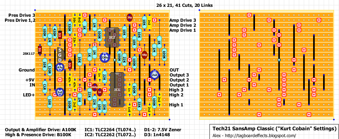
Sansamp GT2 California hot wired only
12


12
Re: Sansamp GT2 California hot wired only
|
I want to sidetrack this....
Can I know more about how you put the print-out of the vero board on the board to put it together like your picture above!!!! Is that the exact size you are printing out or do you have to adjust it to match the vero board actual spacing???? Chris |
|
In reply to this post by aelling
It's not verified.
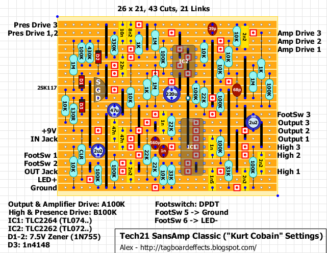
 True Bypass version: 
|
|
Thank you very much Alex. Unfortunately I don't have all the parts to build this yet, I have to go over what I need this weekend so I can start on this one. Build the one on the main site, I didn't write it down but I remember a couple of pots that where wired backwards, can't remember which though. But thanks regardless.

|
|
In reply to this post by Alex
Got the parts including the W100K pots like the original. Build it today, Amp Drive pot is wired backwards so reverse lugs 1 and 3. Also, does the pinout match in the layout for the 2SK117? I think you need to swap D and S.
There is also something else wrong with this layout, if you have the Amp Drive pot on full, you can only get to about halfway point on the Presence Drive pot, once you go beyond that it starts to get an awful high pitch oscillation. Is there something you can do about this? I also got this problem with the layout from the main page and once I got that result from that build, I went on eBay and found an original (pre classic) to see how different it was from the layout. The original of course does not do this, but once you crank Amp Drive and Presence Drive to full on it, it almost starts to oscillate but it doesn't. Any help to fix this would be great. Otherwise, thanks alot for this layout  This layout will fit nicely into a 125b enclosure, I didn't do battery but there should be enough room for one. This layout will fit nicely into a 125b enclosure, I didn't do battery but there should be enough room for one.

|
|
This post was updated on .
Apart from the Amp Drive pot and the transistor that need to be reversed there's nothing wrong with the layout.
It's impossible to reverse-engineer the original pedal for the way it has been built. The schematic that someone (not sure who) has drawn had a lot of guesses. |
Okay, I think I found the error. If you look at the schematic sw3 adds a 10K resistor parallel to a 1M resistor and a 2n2 cap going to Amp Drive 1 (or 3 since it was reversed), but it looks you either forgot the 1M or thought it switched between a 10K and 1M resistor. Anyway, adding the missing 1M and it took away all of that high pitch whistle, it still kinda get start to whistle but it's only when you go fully clockwise on the Presence Drive and with the Amp Drive full on, it's not like before where when you got over halfway on the Presence Drive it would start to whistle. Also, I found that this pedal really needs a buffer infront of it, that also gets rid of the oscillation I was talking about. I wish someone else who has the original would help, my original is old with crackely pots and stuff but it sounds like this schematic has alot more high end than my original, though I dunno if that is because I build the true bypass version or not. |
|
It wasn't a mistake.
When Sw3 is in the "ON" position you add a 10K resistor in parallel to the 1M. That gives you 9K91. |
|
Okay, how that works is beyond my understanding, but like I mention above adding the 1M got rid of almost all of that high pitch whistle/oscillation.
I'd hate to ask Alex but could you make this layout but without the buffer? I am wondering if that is needed when you make it true bypass, and also if that particular buffer has anything to do with the oscillation, perhaps a different buffer will work better. |
|
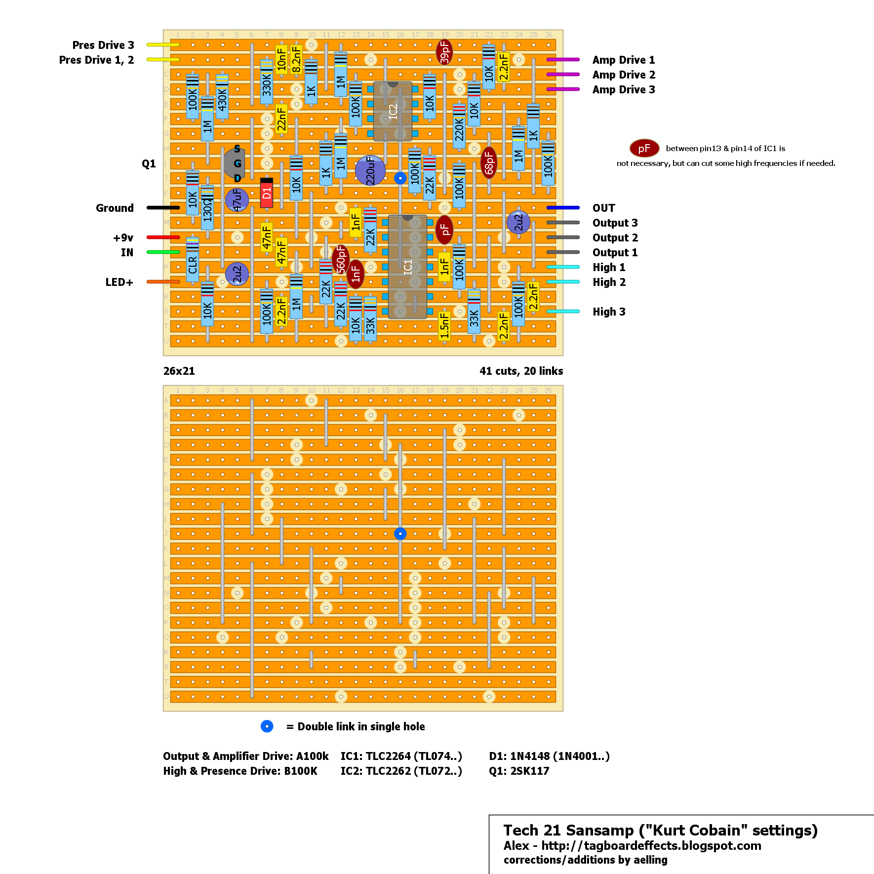
Okay, so I copied your layout Alex for the sansamp and made some corrections/additions to it to make it sound like my original sansamp, and this should be it. First the High pot was also wired backwards. Second, according to Frank_NH the zener diodes wasn't necessary. Third, was the 10k resistor of pin 7 of IC2, that was way to low and clipped the signal when both amp drive and presense drive was all the way off, it didn't clip on my original so I upped it to 220k. Fourth, is the pF capacitor between pin 13 & pin 14 on IC1 was added, it's not necessary butit can cut some high frequencies if needed, I think I went all the way up to 330pF and it still sounded exactly like my original.
So with those changes that would be "teh kurtz" sansamp settings. Thanks again for all your layouts Alex, I with I could help with the original sansamp layout but once I reversed the High pot that is also wired backwards it stopped working so I just gave up on it and you posted this layout which was why I wanted to build one it the first place, to try Kurt's settings. 
|
Re: Sansamp GT2 California hot wired only
|
..... Verified??? Does it sounds like a original????
|
..... Which one???? |
Re: Sansamp GT2 California hot wired only
|
Hi, aelling!... Your version :)
|
|
Yes, the layout is verified. I used the TLC2262 & TLC2264 ICs (dunno how it sounds with the TL072 & TL074) and it sounds pretty dead on compared to the original using the Cobain settings.
|
Re: Sansamp GT2 California hot wired only
|
This post was updated on .
... "it sounds pretty dead" ... It means it sounds the same?
Your recommendations with capacitor "pF" between pin13 and 14 in IC1? |
|
Yes, pretty much the same. As I mentioned in the post with the layout, that cap is not necessary but it helped cutting some high frequencies. I used a 330pF between pin13&pin14 and it still sounded the same, use a socket and try some out to see if it's something you want or not, start with lower value pF's but stay under 1nF, I tried 1nF and it changed the sound too much.
|
Re: Sansamp GT2 California hot wired only
|
Ok!!! Thank you for info!!! )))

|
Re: Sansamp GT2 California hot wired only
|
In reply to this post by aelling
Hi... I have the trouble... No sound! Only unpleasant whistle!!!(
Сould you tell the voltages on IC's and jfet????? |
|
What IC's & JFET are you using? I see that the JFET is probably backwards because that is how the pinout on my non-Toshiba 2SK117GR are. For the whistle, try putting a buffered pedal like a BOSS or if you have a buffer pedal infront of this one, it helps with the whistle for me.
These are my readings for the layout I posted above. PSU: 9.86 Q1 S: 5.56 G: 2.61 D: 9.63 IC1 pin01: 5.30 pin02: 5.30 pin03: 4.84 pin04: 9.63 pin05: 5.18 pin06: 5.31 pin07: 5.32 pin08: 5.34 pin09: 5.36 pin10: 5.26 pin11: 0.00 pin12: 5.12 pin13: 5.59 pin14: 5.25 IC2 pin01: 5.33 pin02: 4.76 pin03: 1.90 pin04: 0.00 pin05: 5.00 pin06: 5.25 pin07: 5.42 pin08: 9.63 D1 A: 0.00 K: 9.63 |
Re: Sansamp GT2 California hot wired only
|
Hi... Thank you! Solved! Now It works!!!)))) I used 2262, 2264 and 2sk117
I fixed two wrong soldering errors!!! I have the whistle when "Pres. Drive" on maximum! Finally Im happy with it!) Today I will test optional capacitors 
|
«
Return to Booster, OD, Fuzz, Distortion
|
1 view|%1 views
| Free forum by Nabble | Edit this page |

