So I've been doing a lot of reading to better understand circuit design, reading schematics, etc, so I'm finally understanding pedal design and what certain changes can do, etc. So I was hoping someone could look over some notes I've made on the Dr. Boogey Schematic, and Verolayout to make sure that I'm actually on the right track. And I'm being honest that I analyzed both the schematic and the verolayout instead of looking for it done already.
I put a note on the page with the verolayout and just tried to figure it out myself, but would really like to make sure I'm right so I have a place to make some mods and really customize it to my liking.
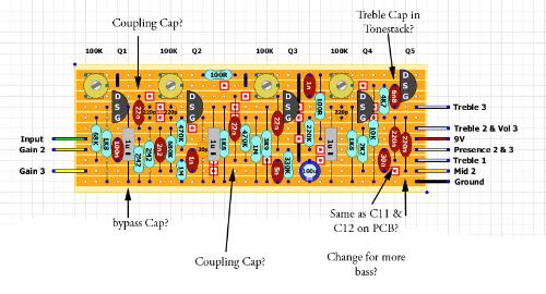

Ive played with one a friend built on PCB, I'm looking at trying to increase the bass output, and make the treble control a little more controllable. But found on DIYSB forum the following changes are benifical, but not sure what all of them do, so I figured it would be good points to begin working on.
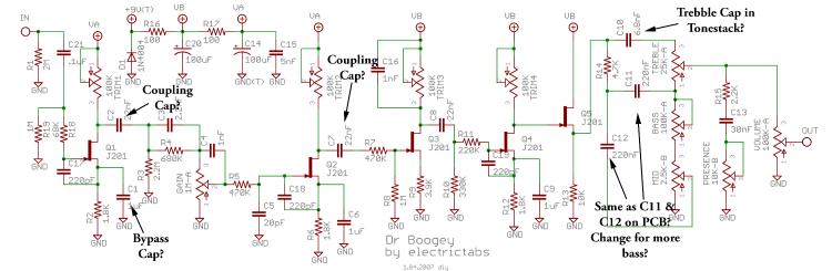
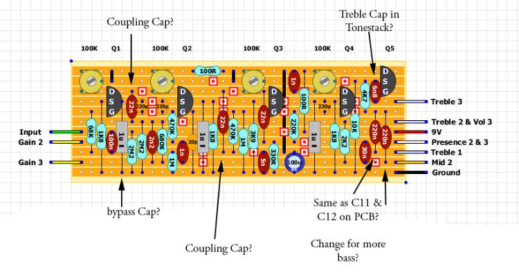
"If you build a gaussmarkov and want more bass, you can enlarge C11 and C12. Ideally you could socket these to play around with values, but I really like a 1uF in C11 and a 0.5uF in C12. Sounds great to my ears like this, and I play big beefy stuff so I need lots of bass. A 10nF cap across the volume pot worked (as listed below) wonders for me in combination with what I said already. The treble can be dialed in really well now on mine. Here's some other mods I've read on this forum:
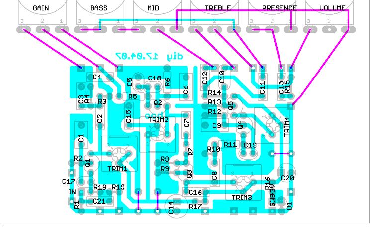
- build a standard DR boogie with gaussmarkov´s PCB..
- Replace the first coupling cap (after the fisrt fet, 22n) to 4.7nF
- replace the first stage bypass caps for two caps, 10uF for "modern", 220nF for "Raw", none of them for "vintage", switch between them with a spdt On-off-on switch
- replace the second coupling cap for 6.8nF or so
- Change the treble cap on the tonestack (6.8n) for something smaller (2,2nF or so)
- use 2 250k pots for volume A and Volume B, i only switch the output of them with one side of a dpdt, the other side controls the leds
- put a 10nF cap between lugs 1 &3 of one of the volume pots (doesn´t matter which one) to eliminate most of the harshness.."
Thanks for all the help so far guys, and thanks in advance for any help you can give me on this project. You guys are the best.