Schematics for noobs

12
12

|
Hey Guys,
I sort of asked about these things before, but I'm just having a hard time grasping how to read schematics and therefore really understanding what everything does. I'm gonna go all out on embarrassing noob-assumptions, so if anyone has the time or will...bare with me. I have tried many things, buying books for beginners/electronics for example. Everything is explained easily, I have to do tests with batteries, finding out what part of my body resists more to find out what a resistor does. Which I shamefully do because I need to start at the basics, right? Only to turn the page, and BAM: Transistors explained and I have no idea what they're talking about. Pumps and things flooding, I have no idea haha. In some books I actually checked if there were pages missing, you know? "Compare it to cars in trafficBAM formulas!" Now I'm not trying to take shortcuts, and maybe my brain is not meant for it, but for some reason there are things that just won't 'click'. So I thought: I'll breadboard stuff. Exchange a few components and see what does what. No sound though. Trying to put the legs further in, only to bend them and fighting with parts to see if they locked in the breadboard or not. Still nothing. Maybe it's the glue on the part-legs that stops it from making a connection? The simplest circuits. Because there's no one who can can tell me what is wrong with it, and english not being my native language so I feel i'm googling wrong questions, I get tired after a while and build a schematic to keep it fun. So onto the next: Reading schematics. I started with the page where they explain the linear booster. That's great. Input, pulldown resistor I guess, Cap to block DC, voltage divider to determine how much power goes to the transistor, R3 and R5 are harder to understand, but connect the transistor to 9v and ground, so I guess it sort of works the same way as the voltage divider before the transistor, only to determine the output of the transistor itself? Then a cap to block DC again and a volume/resistor that determines how much signal goed to ground and how much to the output. Not perfect, but an ok grasp of what it is doing maybe? So I'm looking to expand this minimum of knowledge and take it to the next step. I have been searching for simple schematics, but I just get stuck every time. I think it's because I can just not grasp the signal flow. I see it from left to right as it does in the LPB-1. As in: the signal follows the trail and I get thrown off if it does weird things haha. I'm looking at the electra schematic now for instance. It's embarrassing, but I just don't see it. Input, Cap for blocking DC and filter for bass frequencies. Then.. eehm..the signal goes 2 ways? Following the trace, it goes through the 2m2? To where though? And to the transistor as well? Or doesn't any signal go there cause it's not powered yet? From what I'm guessing is that the transistor amplifies the signal, and it gets send into the transistor again through the 2m2 resistor. But what about the signal that would travel from left to right through the 2m2 resistor? After that I guess DC filtering again? And then the diodes.. I have no idea how to read that. I would say the signal goes from left to right, why would it be affected by the diodes? Isn't the signal like: "Hey, I'm travelling from left to right in the schematic, if I'm gonna bump into to a diode the prevents me from going to ground, I'm not affected by it.." The the volume and we're at the end. Is there something that's even simpler than this circuit so I can finally understand? Im really sorry for this super long story, it's basically just my train of thought, blurting everything out in an embarrassing way, but these are the things that just don't seem to click in my head. Hope someone is still reading this and can give me advice :D 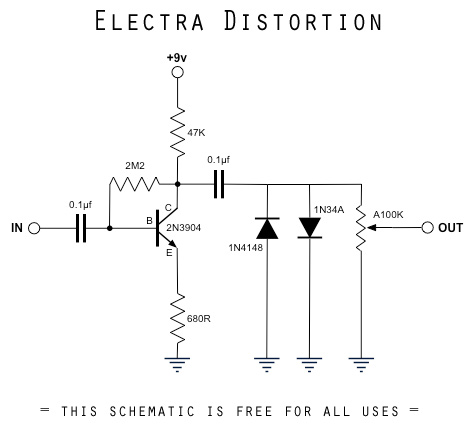 |
|
Administrator
|
First off, I wouldn't have guessed that English isn't your first language, so you're probably doing a lot better than you think with your English.
Secondly, rather than trying to understand the technology of the transistor itself, you may benefit more from looking at basic transistor configurations. The one that we use most commonly is called the common emitter amplifier. If you google "common emitter amplifier" I think you will find a lot of good info. I would try explaining more but I think there is better info than what I can provide already available online. So to answer your question, what is more simple than the electra and LPB, etc? It's the common emitter amplifier. |
|
|
I'm in the same boat, kinda picking things up along the way but still get mega confused. I found this site really useful tho, if you have a dig around there is a bunch of info on what the components in the big muff do, and what effects changing the values have www.kitrae.net/music/big_muff_guts.html |
|
|
This is also useful http://www.electrosmash.com/big-muff-pi-analysis |
|
|
I am very far from being knowledgeable on electronics but I think it would help you to think of the circuit separately in terms of DC and AC (the signal). For example the 2M2 resistor is performing 2 functions, at a DC level it is regulating the correct bias current to make sure that the transistor can amplify both the positive and the negative parts of the AC signal, at an AC level it is also providing some negative feedback from the collector back to the base to regulate and stablise the gain of the transistor. Looking at the diodes, they have no DC purpose since any DC from the transistor output is blocked by the capacitor, from a AC point of view they are being used to clip the signal which provides the distortion. The way it works is although diodes conduct when the have a forward voltage applied to then they only do that when the voltage exceeds a certain amount (the forward voltage) so up to this voltage they have no effect, past this point there is no further increase in voltage so the top is clipped of the signal. By having 2 opposing diodes, both top and bottom are clipped, also since they are different types of diode the forward voltages are different which causes asymmetric clipping (top and bottom are clipped at different points.Please anyone who has more knowledge - correct anything I have got wrong!
|
|
|
In reply to this post by Travis
Wow guys, thank you all so much for reading it and replying! Such a great forum/community this is!
The transistor is a great tip! Already found some stuff, and being the most important part in a circuit, it only makes sense to check that out first. And thanks for the compliment! I try, am from Holland but have a Canadian gf, that helps! The muff looks daunting and intimidating... coming from trying to understand Electra's and Devi, it's quite a huge schematic! But very useful when I actually read it. It's good to know what effect things have on the sound. The DC and AC went over my head unfortunately.. I think I have an idea and have read about it ofcourse, but how to see it in a circuit is hard to do for me now? Thank you guys a lot! My answers feel to be too short to seem grateful, but I am. There's already so many things I can look into now cause of everything you guys provided. I just really want to get this you know? I drank away a lot of braincells, but used to do ok in school. It must be possible right? :D |
|
Administrator
|
Regarding the AC and DC thing, it's important to remember that capacitors allow AC to flow through but block DC. So when you use an input capacitor, the AC signal from your pickups flows right into the base of the transistor, but the DC voltage present at the base is blocked from going into your pickups.
Likewise the output capacitor (from collector to vol 3) is preventing DC from flowing from the collector to the volume pot. In a circuit with multiple gain stages, you will usually see a capacitor used to couple two gain stages together. This is done also to prevent DC bias from one stage from affecting the DC bias of the next stage. So you can see that capacitors are used to move your AC (guitar) signal though the circuit while isolating the DC bias of each stage. The second purpose of the coupling capacitors is of course to shape the tone. Each capacitor forms a high-pass filter where low frequencies can be attenuated depending on the value of the cap |
|
|
In reply to this post by Marbles
The Muff looks daunting, until you realize its basically 4 separate gain stages in series, with a tonestack between stage 3 & 4. Once you realize that the Muff schematic can be chopped into separate sections, each nicely in series, it becomes easy to understand.
Its too bad though that the Beavis Audio website is offline. He made understanding electronics and schematics look easy. Hopefully this works. Understanding_Schematics.mht |
|
|
Can beavis audio be found through way back machine???? I'll see if it's on there. |
|
|
It seems to have been archived here at various times over the last few years http://web.archive.org/web/20150315020519/http://www.beavisaudio.com/ If you search http://www.beavisaudio.com/ from the main page you get a whole bunch of hits. |
|
|
Regarding the AC & DC thing - generally AC is what we are interested in - the guitar signal and DC in these circuits is generally your power supply/battery but can also be bias currents/voltages which are needed to get the active components (transistors/opamps) working correctly. As stated above it is in capacitors (and inductors if they are used) that the distinction is most obvious - generally capacitors block DC and pass AC although the degree to which they pass AC depends on the frequency of the signal and the size of the capacitor (amongst other things).
Not sure if that helps at all - my wife says I am every pupils nightmare when it comes to explaining things so I understand if it doesn't. 
|
|
|
In reply to this post by PMowdes
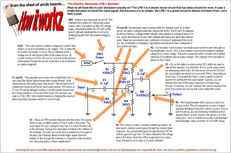
Beavis was a great resource to understanding, and moreimportantly using the theory side of how circuits work: The "How a booster (LPB1) works" on the tech pages is a nice layman's explanation of a transistor gain stage and is applicable to many other variations (e.g. BMP stage 1-3) |
|
|
This link >>>>> http://web.archive.org/web/20150414091249/http://www.beavisaudio.com/techpages/ |
|
|
In reply to this post by scimitar
Wow, this is awesome you guys!
I'm having real long days at work, and no time to reply during the day, but man, I have learned more in the last days than in the 2 years building them! I kinda starting to grasp the Ac Dc thing maybe. Your explanation is good, don't get me wrong, it's just hard for me. I'm used to, well, guitar signal you know? Guitar signal goes in a pedal, moves on to the next, then something happens there etc to eventually go to an amp. So when I'm looking at lines in a schematic, I just see an audio signal, cause I'm used to that. I follow the schematic, and think: Alright, the guitar signal goes through here, then with all the stuff to ground and 9v it's hard to make sense. Slowly with all your help, I'm getting to understand little things. I guess I should see AC as the signal I'm familiar with. That comes into the input, accompanied by DC. With a cap, we filter out the DC so we only have AC left. Then usually, that same cap forms a high or low pass, (depending if the resistor is before or after the cap?!) and goes towards the base of a transistor. To bias the voltage to the transistor base, we create a voltage divider by having a resistor from 9v to base and from base to ground. Because of that (the 9v), we introduce DC to the circuit again and that's why we filter it out again after that stage?? The muff schematic does help alot how I should view the schematic. I'm starting to understand the tone stack of it vs the 'usual' one. And it is indeed obvious now that every 'stage' is separated by another Cap to block DC. When seeing schematics now, it's easier to separate the different stages and it makes it less chaotic. The feedback resistors are not something I get though. And there is no obvious voltage divider and a lot of resistors around that transistor that i don't understand what the hell they are doing haha. Been reading a lot, or trying in the little time I have, on the common emitter amplifier. Like Travis pointed out, I feel that there lies the key in understanding 80%. It's just... hard :D Making it's work that's not letting me focus enough, but every tutorial is full of vce vcc, other abbreviations and formulas that it's hard to keep up. I will hang in there though! Thanks all so much. Happy to see the beavis stuff is to be found still. Will def check all the links. Thanks for hanging in there with me! :) |
|
|
I don't know exactly what to tell you, but I am also a self-taught beginner, so what I say is coming from basically the same place you are coming from, but I think I grasp a little more (though I still have a lot to learn).
1. Whenever effect pedal designers refer to AC, they are referring to the audio signal. This is because audio is a full 360-degree waveform that goes positive and negative). Whenever they refer to DC they are referring to power (the battery) that makes the pedal components work. Think of a pedal as having a DC voltage to power an AC audio signal. Dc is generally considered to be half of a sine wave (180-degrees) of power. So, the important thing to understand is that all power in a pedal is DC power (converted from the wall AC 120v source through a transformer, or 9v DC from a battery) So, when you see a schematic, look for four places first: 1. input (audio) 2. output (audio) 3. DC voltage + (in most cases, some fuzz tones use reverse voltage but that is a complicated topic to worry about later) 4. Ground So - the source of your DC power, represented as a battery in most cases, will have one side marked +, and the other side will be marked GROUND (the lines that form an arrow shape). Remember that all ground points in a schematic are connected, but they don't draw them that way. They use the ground symbol as a shortcut to represent that connection. When they use components, such as a resistor or capacitor, they may be used to manage either the power or the signal, or sometimes both. For example, a capacitor blocks DC, so it is a good way to filter power-related noise out of your audio signal. Learn to follow the audio input signal from the input (there will generally be an input AND a ground, but follow the input) and look for devices give gain (transistors, ICs). Look for RC filter combinations (a resistor combined with a cap) and understand that those are tone controls (Bass, mid, treble) that work by filtering out certain frequencies to pass to ground. A high-pass filter lets treble through, low pass lets bass through. Look for feedback loops, especially with ICs & transistors, which are often used to create gain - the loop usually goes from the output of the IC (the right-side point of the triangle) back into one of the inputs; normal or inverting. Transistors also have feedback loops, in your schematic from the C out thru the 2M2 resistor back into B. Understand that diodes are usually used in pairs to change the audio (AC)-waveform. They limit voltage and hence cause the waveform to clip, but they can only clip one side of the AC audio signal, so you generally use a pair, one to clip the positive side, the other to clip the negative side. They flatten the waveform and make it "harder" changing it from a bell-like sine wave to a more harmonically complex square (distortion) waveform. You can vary the profile of the wave by using different diodes in different combinations. There are other ways to make sine waves into square waves; overloading a transistor or IC, for example, beyond its normal range of audio "fidelity" (on purpose). So, looking again at your schematic: The first cap is a high pass filter, so you circuit is not over-burdened with low end (low frequencies tend to be more powerful than higher frequencies, and you can clip a circuit with low frequencies you can't even hear, which would not be a very effective circuit) The signal does appear to go two ways, but keep in mind that the feed coming off the transistor through the 2M2 resistor is far louder than the input, so that junction really is adding more signal back into the transistor (this is creating a feedback loop from "C" to the 2M2 and back into B). Such loops are where gain comes from. The 680R is a feedback stabilizing resistor which determines how much gain you get from the feedback loop. The .1uF cap (aka 100n or 104) is there to remove the battery's DC from the audio signal. The diodes are there to add clipping to the audio waveform; it is asymmetric clipping because you are not using matching diodes. They say the key to building an overdrive is to manage the voltage (increasing signal to get clipping, or adding a transistor to recover any signal you lose by adding filters) and also managing the low end, which tends to build up more noticeably than higher frequencies every time you boost gain within a circuit. Your circuit does not have a recovery stage after the diodes, but a lot of other circuits would add one. Other circuits put the diodes in the feedback loop. The output is a simple variable resistor where your volume is controlled by changing the resistance the signal sees before it goes out. If you decrease the resistance, the sound gets louder. When you see thing like VCE or VCC, they are usually referring to the given voltage a certain stage and if you see one VCE, someplace there should be another one - consider these two point to be connected - it is a shortcut to show you sections of a circuit without having to draw all the lines. |
|
|
It's pretty easy to figure out what various components do [to an electrical current] in isolation but sometimes, collections of otherwise easy to understand components seem very abstract. We can express all this mathematically, but for the amateur, it's hard work and still prevents us from visualising what exactly is going on, which for me is the biggest hurdle.
One of the biggest helps to me was from Beaker, explaining the big muff circuit as a set of 'modules', separated by coupling caps which only pass ac [the derived signal from the guitar/bass] into the next module, then each module being further constructed of smaller commonly used 'modules', such as voltage dividers or, as in this case, a common emitter amplifier, which is itself ccomprised of smaller modules, for example, the collector and emitter of the transistor is in the centre of a voltage divider. From this, I got into reading about voltage dividers, low pass and high pass filters and the like, which then helped me simplify layouts and schematics a little by recognising small groups of components and thinking of them collectively as a single entity. When you get to this point, you start to 'see' things like the common emitter amplifier and even more complex circuits like the big muff in a completely different way. Another couple of things that I think are important to understanding what is going on in the stuff we play with are: Electricity actually flows from negative to positive, electricity will flow through the path of least resistance and ac & dc, if combined in the same circuit or wire, will combine and [as long as the dc is of a higher voltage than the ac] fluctuate but will remain positive. The transistor in this example [common emitter amplifier] is the magic box. Simply put, a transistor controls a larger volgage [in this case the dc through the emitter/collector] from a smaller voltage from the combined ac and dc signal at the base. So, the ac and dc is combined and adjusted by the bias resistor (some circuits set the bias by using a voltage divider, so look out for that :)) to set the bias voltage at the base. Fluctuations of the ac, within a very narrow range within the combined positive charge allows current to flow between the emitter and collector, which is a higher voltage than the bias signal voltage, but reflects the fluctuations seen in the ac signal, thereby causing an amplified signal at the collector. I once read that a transistor is like a 'magic pot'. So if you visualise you guitar signal [ac fluctuating up and down to reflect the guitar signal sine wave] as an invisible hand frantically turning the 'magic pot' up and down in response to the peaks and troughs of the signal, constantly, changing the resistance thereby changing the output to match the sine vave but at a higher amplitude, you essentially have what a transistor is doing. Without getting into the physics of things like capacitors, transistors and opamps and learning about some pretty heavyweight mathematics, I think we need to accept that components are for the most part black boxes. This doesn't seem like an obstacle, because we can see in laymans terms what is required to put in and what we should expect to get out of these things. What is more important in my opinion, is understanding how these components combine to create larger modules or functions within a circuit. This has certainly helped in my case. Thanks again Beaker :) For the record, this stuff isn't easy for the casual amateur. :) And by all means, please feel free to correct anything that I've stated in error. But please be gentle... |
|
|
My recommendation for learning more about how circuits work - besides reading all the basic electronics information there is out there - is to learn how to use the LTSpice circuit simulation software. It's free to download, and you can build nearly any circuit you like and see how it performs in terms of AC and DC voltages and currents, frequency response, and wave shapes (i.e. a virtual o-scope). I recently used it extensively to design an amp sim circuit (which I will post here in due course), but have simulations of a tube screamer, distortion +, and even the entire ROG Britannia! Here's the link:
http://www.linear.com/designtools/software/ |
|
|
In reply to this post by motterpaul
@ Motterpaul Thanks so much! This was really helpful too!
It's nice to be walked through a circuit like this, and especially the line about the feed from the transistor being a lot louder is very important for my understanding. It shouldve been obvious, but it wasn't for me until now and that's another invaluable piece of this puzzle. The diodes are still hard to grasp though. I mean, from my point of view, the signal coming from the cap and going to the output/pot would be stronger than going down through the diodes towards ground. Especially the first one. I would think the signal wants to go there, but can't, so it has no effect. As you see, I really am a beginner. But your advice is awesome, thanks! |
|
|
In reply to this post by Ed Nice
It really isn't easy haha, especially for me. I really appreciate all your help. I was tired of not getting it, so I just decided to put aside all the shame and just ask even the stupidest questions.
The Big Muff does really help. And that helps to understand oher schematics somewhat. To find the balance between what is necessary to understand and what not is hard. That's the problem what I have with most basic electronics books. After a quick introductions, it's mostly mathematical formulas right away. It's not that I don't want to learn that eventually, I just am not sure how much of that is necessary for now. So i'm taking all of this in. My goal is just to be able to understand what component effects what in the circuit. Your guys help helps a lot, so thanks. |
«
Return to Open Chat
|
1 view|%1 views
| Free forum by Nabble | Edit this page |