Seppuku Space Fuzz terribly mis-biased

classic Classic list List threaded Threaded
2 messages Options
Reply | Threaded
Open this post in threaded view
|

Seppuku Space Fuzz terribly mis-biased

Digitalzombie


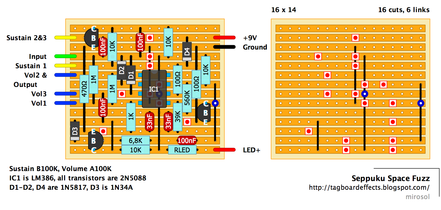
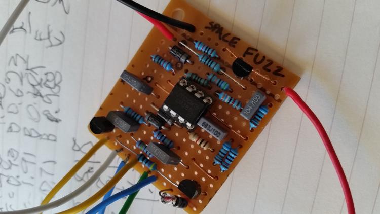
Using the layout from the site. The only substitution I made to my layout is using a single 68nF instead of the two parallel 33nF.

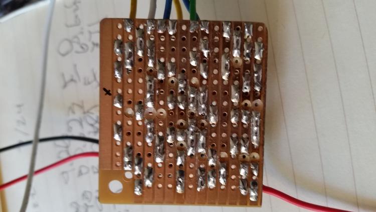
I've checked continuity multiple times and I can't find any solder bridges.


Voltages are as follows:
Source: 9.49
After diode: 9.26

Q1
C: 0.73
B: 0.623
E: 0

Q2
C: 1.91
B: 0.685
E:  69.6mV

Q3
C: 0.71
B: 0.988
E: 371mV

IC
1: 1,524
2: 57mV
3: 0.53
4: 0

5: 8.18
6: 8.1
7: 4.3
8. 1.533

I'm sure my problem lies at the output of the 386 at pin 5, but I can't tell why that voltage is reading so high.
Reply | Threaded
Open this post in threaded view
|

Re: Seppuku Space Fuzz terribly mis-biased

BetterOffShred
I socketed the resistor in the bottom left corner because I wanted to try things, it fell out, and then I put it in backwards and it sounded shitty.  Maybe try a 1n4148 just to see..  

Also this pedal kicks was with a B2k sag pot in series with the 9v supply. Its amazing.