Sola Sound Tonebender Mk III biasing
|
This post was updated on .
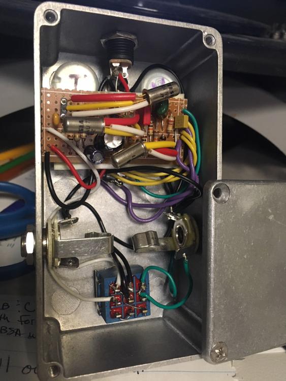
I just finished up a Sola Sound Tonebender Mk III (layout) - using Tesla 104NU71 NPN Germs. I reversed the caps, etc., and used the stock values on the layout - and went with 60/62/123 (.21mA lkg), and it fired up through my test box right away.
Boxed it up tonight and started playing with it, and noticed some ugly fuzz sounds with long held notes (glitchy sounding on the decay) - that I hadn't noticed through my test rig. Knifed strips, checked everything, etc. - and it seems to only happen when the fuzz is maxed, or on long held notes/chords. I took bias readings to compare against what they "should" be - but I can't seem to find any info on what the trannies should bias to.  Q1: C - 3.096 B - 1.609 E - 1.544 Q2: C - 3.013 E - 1.445 B - 1.544 Q3: B - 0.051 C - 0.056 E - 0.00 So - Q3 doesn't look right to me, but I'm not sure what I should be aiming for. The circuit sounds pretty decent, it's just got some gating/decay that I'd like to get rid of. I thought about replacing Q3, but before I start tearing into it, I thought I'd reach out to the helpful gang here... Any ideas/suggestions? Thanks! EDIT: I pulled Q3 and checked it on my DCA55 - and it showed an hFE of 6 (?), then I let it sit and measured again, this time hFE read 137. I swapped it out for another 103NU71 (hFE120, lkg .39) - and it's better, but it's still got some slightly unpleasant artifacts when the note fades out. New voltage readings for Q3 below, and my question still stands - what should the bias target(s) be for Q2/Q3? B - 0.00 C - 3.6 E - 0.00 |
|
Administrator
|
My DCA55 has been doing that too because the battery is low in mine.
From my Tonebender. I don’t know which is Q1 or Q2 on the PCB but I can tell which one is Q3 which seems to be most relevant here Battery: -9V Q3 C: -3.25V B: -0.05V E: 0V If I had to bet I’d say you’re probably using loose sockets to hold the transistors which are not making good contact. |
I just replaced the battery this weekend. I double-checked it, and it's still up near peak charge (no pun intended). I trimmed the legs of the new transistor (104NU71, 120/.39) just a little, then flattened the ends with a needle nose to get a nice tight fit in the sockets - then I put just a small dab of solder at the top of the socket to hold them in. Plugged it in, tested voltages... C - 3.6 v B - 0.02 v E - 0.00 so, a little better (getting a reading on the Base) and the artifacts aren't as prevalent or annoying - but they're still kinda there at the end of a decaying note. I'm going to try futzing with the value of the 18k resistor (top rail to collector) - socket some higher values and see if that has any effect. I went back and tested the original transistor I had in there: didn't touch it, used a needle nose to pick it up and attached the Atlas leads, tested, then let it set for a while. First test: 140/.43. Second: 0/0. |
|
Administrator
|
I’ve been down this road many times before (as you might guess based on the fact that I immediately knew what your problem was without you saying anything about it at all).
The sockets are just a bad idea for pedals with Ge transistors. Especially if you use the horrible sockets from Tayda. The only way to make them totally reliable is to solder every transistor pin, at which point you have eliminated the purpose of using a socket in the first place. If you were to put your original set of transistors that you liked in the pedal, and solder every transistor pin in, it would sound the same as it did when it was working correctly (unless you just didn’t notice unpleasant sound characteristics at that point). Changing the Q3 collector resistor seems like kindof a random and misguided thing to do personally |
And this confirms it. After I posted my response, later that evening, the realization that I was defeating the purpose of using sockets by soldering them in finally occurred to me. The only reason I would do it would try to get a better bias voltage on Q3 - thinking that, if I tweak that voltage, it would (potentially) eliminate the weird artifacts. Thought I read somewhere that there was a target bias voltage to aim for on Q3, but couldn't track the info down - I ended up just boxing it, and decided that If I really want to experiment, I'll breadboard or build out a test circuit - good practice. Sounds pretty smooth, actually.   |
|
Administrator
|
Did you solder in all 3 legs from each transistor? I’d definitely do that before boxing up. Only soldering one leg per transistor doesn’t fix the problem in my experience. When the pedal moves the other legs can still lose contact, even if it looks like they’re obviously touching the socket
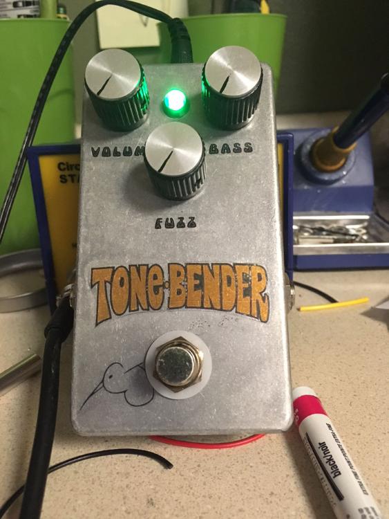
If you haven’t done that yet I think you might be surprised it might just fix the problem completely unless it’s an issue with transistor selection (which it doesn’t really sound like) I like how you decorated your build. Nice job |
Yep, it doesn't look like it from the photo, but they're soldered. And it's the last time I'll be using the sockets, so... Thanks! Waterslides and slightly polished aluminum, semi-gloss clear coat - kinda going for that 'aged enclosure' look, and I think it turned out pretty nice. Made the mistake of doing a demo for my guitarist friend when he stopped over last night, and he "borrowed" it for testing purposes... Off to finish the DAM Fuzzsound and the Park Fuzz 3 knob! |
«
Return to Debugging
|
1 view|%1 views
| Free forum by Nabble | Edit this page |

