Spaceman Effects Nebula

classic Classic list List threaded Threaded
6 messages Options
Reply | Threaded
Open this post in threaded view
|

Spaceman Effects Nebula

anders
Unverfied at the moment, not sure if I messed something up since it's a big circuit. May need a set of fresh eyes. Now I need to do a sanity check.

Schematic

Reply | Threaded
Open this post in threaded view
|

Re: Spaceman Effects Nebula

PMowdes
Nice work Anders
Reply | Threaded
Open this post in threaded view
|

Re: Spaceman Effects Nebula

brazdj
Getting ready to build this and it looks to me like the Vactrol is pointless. Am I confused or... can anyone weigh in (obviously someone built this since it is verified)?

Thank you for the hard work on the layouts!
Reply | Threaded
Open this post in threaded view
|

Re: Spaceman Effects Nebula

induction
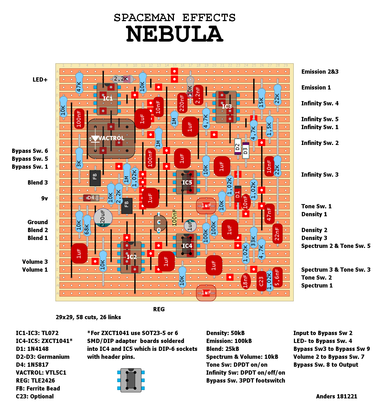
The vactrol changes the resistance between Vref and the non-inverting side of the input buffer. The input voltage on the vactrol is set by V+, not by the signal. It's totally static, which is not how people normally use vactrols in pedals.

When the effect is on, the resistance is set high. This is usually pretty normal, as it prevents high frequencies in your signal from bleeding away to ground through the Vref voltage divider and dulling your tone. But in this case, Vref is provided by a regulator, not a voltage divider, so I don't think that would happen anyway.

When the effect is in bypass, the resistance is set low. This part I don't entirely get, but maybe the point is to hold the buffer output completely stable.

It's worth noting that the vactrol ($2.50) could easily be replaced by a resistor (<$0.10). What's the difference? Switching speed.

My guess: The circuit is noisy AF and dirties up the voltage rails even in bypass, maybe even oscillates. The switch is there to quiet it down, and the vactrol is there to slow the switching down so it doesn't pop. You could probably do something similar using a transistor as a switch (like a variation on the Millennium Bypass).

If you want to know for sure, you could try it without the vactrol to see what the difference is. It looks to me like you could just leave it out and make no other changes (don't replace either side with a jumper or anything), and the effect would be like not lowering the resistance in bypass. If I'm right, the bypass signal could be noisy or unstable. If you rearrange the switching slightly, you could set it up to swap a 10M when engaged to a jumper in bypass. If I'm right, it will pop, but not be noisy.

It's also possible that I'm right about the intent, but it's just a safeguard that's only necessary with dirty power or in just the right conditions. (In that case, the difference would only show up at a gig. ) If you decide to do this experiment, let us know how it turns out.

In any case, go ahead and build it. The vactrol is only active in bypass, and doesn't see the input signal, so it should sound exactly the same when engaged, with or without the vactrol. The only sonic difference would happen in bypass or during switching.
Reply | Threaded
Open this post in threaded view
|

Re: Spaceman Effects Nebula

brazdj
Hello. Verified! Sounds really great. Switch Tone Sw. 1 to Tone Sw. 4. Flip the REG 180 degrees (or for the builder just check your pinout before installing the REG).

Interesting note: Turning Density to either of its extremes cuts out the sound. Given the Triffid schematic not too surprised, just wonder if that happens with the actual Spaceman units.

I played around with the Vactrol and at my house it made no difference whether it was installed or not. I actually heard a very slight pop when bypassing with the Vactrol installed. Switching was dead quiet without it. I will likely stick with the Vactrol, but would recommend all future builders to just a get the cheapest one they can find. The model that is specified on the layout is much too pricey from Smallbear given its function.
Reply | Threaded
Open this post in threaded view
|

Re: Spaceman Effects Nebula

brazdj
My density issue was due was a tiny solder bridge. Doh!

As I was tracing the issue, however, I noted two tiny errors in the layout.

1. The 10K resistor closest to pin4 of IC5 should be moved two rows up to connect to pin6 of IC5. Both pin 4 and 6 of IC5 should have 10k resistors to Vr. Currently pin 4 has two 10 k resistors to Vr, while pink 6 has none.

2. The 1uf capacitor four columns to the left of pin 3 of IC5 should be connected to pin4 of IC5. I did this by connecting at an angle. One leg of the cap goes to where the 10K resistor (that should be moved) connects. The second leg of the 1uf capacitor connects two rows down and two columns to the left (45 degrees) to the left side of the semi-transparent, horizontal 1uf capacitor.