Started repairing things...

classic Classic list List threaded Threaded
4 messages Options
Reply | Threaded
Open this post in threaded view
|

Started repairing things...

Zanius
A friend asked me to see what's wrong with his original Small Clone Chorus, and I felt I had learned enough by now to -maybe- find out what can be wrong in a pedal.Also change the dc socket as the original one has a mini-jack dc input!  Some things were clear to me and I started soldering.

After everything else has been take care of (snapped cable, switch badly wired by some other guy), I gave it a go. Bypass is ok. Effect On lights the led and slightly "pops" (which means the switch actually happens) but it's only clean signal once again. Controls change nothing...

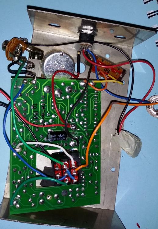
So I started measuring. To better explain I ll add a pic.


there.

That is what I have right now. The effect has a 47Ω resistor straight by the dc input to the board and the led. That's how the schematic is, and original photos have the said resistor there. Now what doesn't add up is that at the dc socket there are 9volts and at the solder ball where it connects with the led cable there are 4,5 volts! All I really don't have to knowledge to decipher what that means. That is the main question of this post i guess. Is there something that could be causing that? (a bad component?)

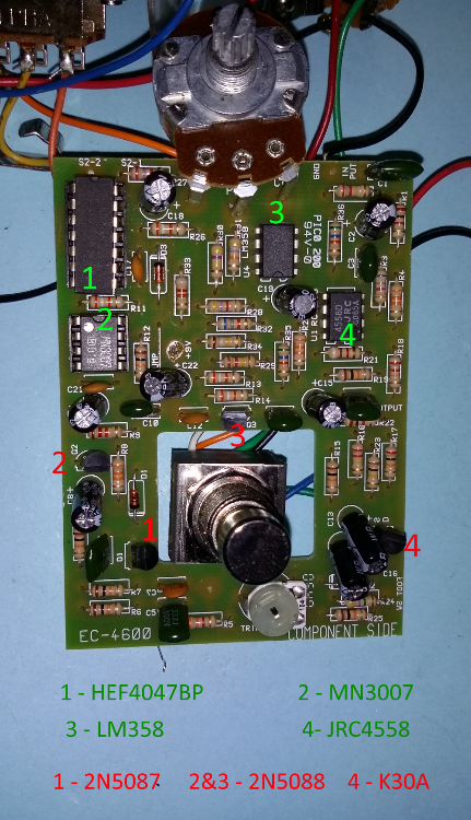
The board has two ic's in sockets (that's very nice of them, lol). The CD4047 and the MN3007. The 4047 was kinda squashed in its socket so i pulled it out, put the feet in order and got it back in. Voltages doesn't seem right around it's feet though. Could that be causing the problem?

   
Reply | Threaded
Open this post in threaded view
|

Re: Started repairing things...

Luke51411
Post the voltages you are getting at all the IC pins and we may be able to guide you to the solution.
Reply | Threaded
Open this post in threaded view
|

Re: Started repairing things...

Zanius
And, to whoever it may concern here are some voltages.


Input 9.3 V

Q1 - 2N5087                Q2 - 2N5088
C - 0                             C - 8.2
B - 5.1                          B - 7.7
E - 5.82                        E - 7.1


Q3 - 2N5088   Q4 - Sk30A
C - 8.2              D - 4
B - 4.7    G - 0
E - 4.6                    S - 4


Ic1 - 4047B (notice i forgot this placed upside down in the picture. Original and measuring placing is facing south)
1. 3.63  -  14. 7.10
2. 3.06  -  13. 6.75
3. 3.60  -  12. 0
4. 7.12  -  11. 3.33
5. 7.12  -  10. 3.33
6. 7.16  -   9. 0
7. 0     -   8. 0

Ic2 - MN3007
1. 7.10  -  8. 5.17
2. 3.30  -  7. 5.17
3. 6.02  -  6. 3.30
4. 0       -  5. 0

Ic3 - LM358 (facing south)
1.*1.50* -  8. 8.20
2. 3.71   -  7.*3.50*
3. 3.27   -  6. 1.92
4. 0        -  5.*2.00*

*On pin 1 voltage is dancing between 1.2 and 2 volts.
  On pin 7 the same between 2 and 5.3 volts.
  On pin 5 between 1.7 and 2.4 volts

Ic4 - JRC4558 (south)
1. 4.03  - 8. 8.06
2. 4.03  - 7. 4.07
3. 3.20  - 6. 4.05
4. 0      - 5. 3.95
Reply | Threaded
Open this post in threaded view
|

Re: Started repairing things...

Zanius
After some snooping around and compering some posted voltages, I kinda made it work. Adjusted the trimmer and now I got some decent chorus when the "depth" switch is on (deeper). On the "off" setting, I barely get some chorus. i guess it can do better. But what is still off?

Most voltages seem fine compared to others found online, except the 3 first pins of the 4047b. Most people get [ 1-9v , 2-0.01v, 3 - 8v ] aproximately. I get  1- 3.6  2- 3.96  3- 3.6.  That doesn't seem right. I guess I will be ordering some chips to test further!