Super 65 debugging help needed

classic Classic list List threaded Threaded
13 messages Options
Reply | Threaded
Open this post in threaded view
|

Super 65 debugging help needed

holm
This post was updated on .
Hi

I'm in the process of building the Super 65: http://guitar-fx-layouts.42897.x6.nabble.com/LOVEPEDAL-SUPER-SIX-STEVIE-MOD-tp36155p42057.html


However there's some funky stuff going on with the signal already at the first transistor. When audio probing, the signal is "ok" at the gate of M1: https://soundcloud.com/erik-holm-nielsen/bs170-gate-audioprobe/s-KwjxR 

But it's really weak and noisy at the drain: https://soundcloud.com/erik-holm-nielsen/bs170-drain-audioprobe/s-3ptXB.

The voltage readings are as follows:

+9V: 7.44V

BS170: Drain: 7.40V  
            Gate: 3.53V
            Source: 2.07V  

2N5457: Drain:3.84V  
            Gate: 0.63V
            Source: 0V

Also, initially I incidentally reversed the D2, don't know if it could be fried? I just reversed it and reused this one. D3 and 4 are orange diodes (2.1V) instead of red ones (2.2V).

Any help is highly appreciated
Erik
Reply | Threaded
Open this post in threaded view
|

Re: Super 65 debugging help needed

Frank_NH
Hi Erik,

Well, this is my circuit, so I take responsibility here...

I've built it (see my build below), and it works fine.  I noticed that your voltage is low:

+9V: 7.44V  <----

This circuit won't work correctly at 7.44 V.  Are you using a battery?  If so, get a new one and try it again.

Another note - the drain voltage on the 2N5457 should be about 4.5 V - 5 V.  I think if you use 9V for the source supply, that should read in the right range.  If, for some reason, it is off, you can adjust the drain voltage by substituting a different resistor for the 4.7K drain resistor (smaller to increase the drain voltage, larger to decrease it) - you can even use a 10K trimpot there.

One more thing, the LEDs should light up while you play.  The orange LEDs will probably work OK, but may give slightly less crunch.  However, this is a low to mid gain overdrive, so don't expect a tremendous amount of distortion - just enough to sound like SRV.  

Reply | Threaded
Open this post in threaded view
|

Re: Super 65 debugging help needed

holm
Hi Frank, and thank you for your swift answer, the SRV sound is exactly with I'm out for  

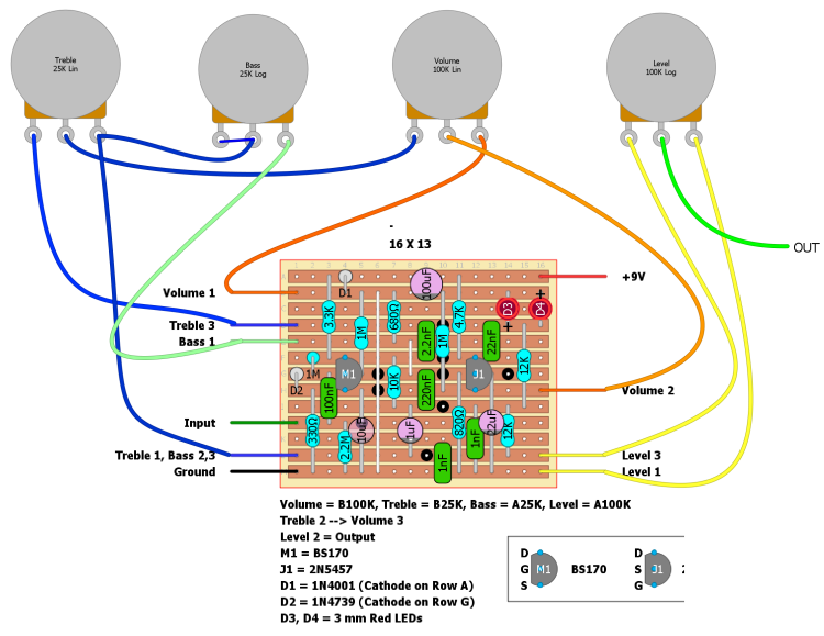
I had a look at it this morning with fresh eyes, and I had the 3mm diodes placed wrong. With that corrected  and a 9V power supply connected instead of the battery, I read 9.1V on the +9V row and also at the drain of the M1.
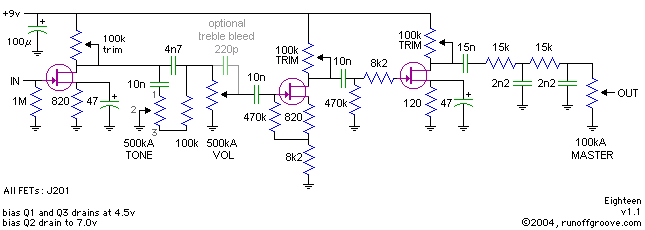
I got a voltage reading of 5.5V on the drain of the 2N5457, installed a 10K trimmer and adjusted the voltage to 4.65V.

Still there's something off!

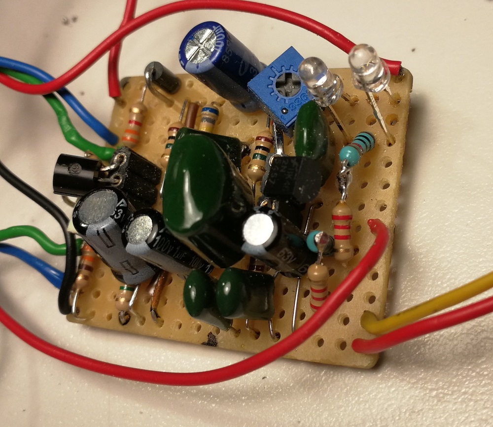
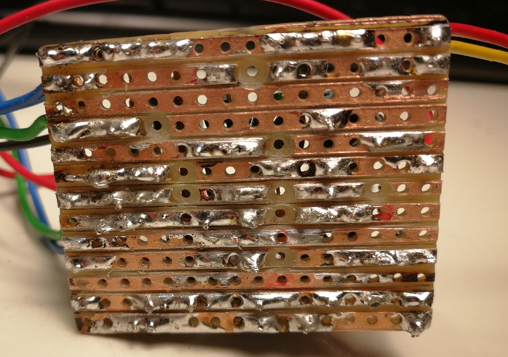
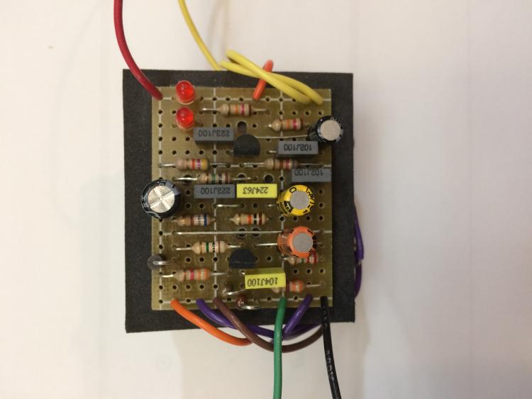
I been over the board a dozen of times now, I have scored the grooves with a blade, but the output is flimsy and noisy!

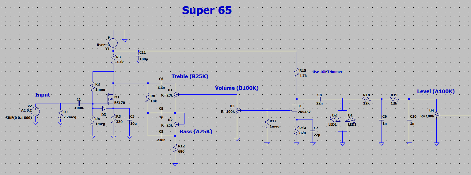
If the 4.7K resistor is the drain resistor of the 2N5457, and this spans from the +9V row to the drain, which results in a voltage drop from ~9V to ~4.5V.

In contrast, there's no voltage drop from the +9V row through the 3.3K resistor to the drain of the BS170! Shouldn't there be a drop in voltage there as well.

I have socketed the transistors, and I'm not sure whether this is working out to well, since I get a lot of popping when touching them! But can you solder them directly without the heat damaging them?  

Furthermore, the treble and bass pots ain't doing what they're supposed to, so I circumvented those and attached treble 3 directly to volume 2 on the board. I'll have to look at that later.
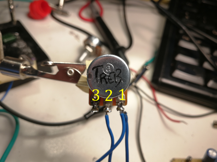
Just to be clear the numbering of the pot lugs is like in the picture below? Thanks again
\Erik


Reply | Threaded
Open this post in threaded view
|

Re: Super 65 debugging help needed

Frank_NH
Your JFET (2N5457) should be OK with the voltages you state.

If your voltage at the drain of the MOSFET is too high, check all of your connections and more importantly the values of all resistors (for example, did you use a 330 ohm rather than 3.3K resistor?).  Post some pictures so we can see your build.  Again, mine works perfectly (including the tone controls) so I know the circuit is OK, and I believe one other person has verified it.
Reply | Threaded
Open this post in threaded view
|

Re: Super 65 debugging help needed

holm
Hello again, and thank you for taking your time Frank, and I'm not in any way questioning your layout, I'm new to this, and obviously need help.

And I'm sorry  
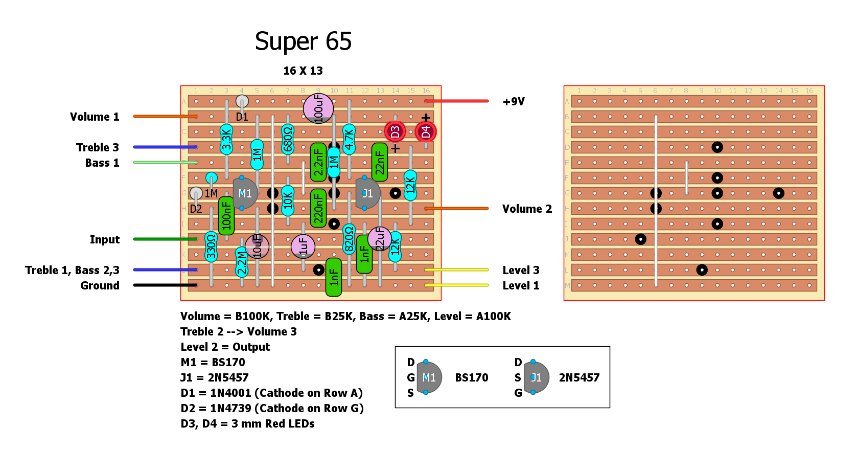
going over the board again I realized I used a 330K instead of a 330R, and putting a 330R in, it know I get a much louder and less noisy output!
I'm sorry for all the hazzle.

However, after installing the treble, bass, and volume pots again, the bass pot does nothing and the treble pot works as a volume! I wired the pots as in the scheme below.


Also here are some pics of the build, sorry for not posting earlier.


I know I'm hopeless at this, but please don't give up on me, I need to make this one to work, Thanks again
\Erik
Reply | Threaded
Open this post in threaded view
|

Re: Super 65 debugging help needed

Frank_NH
Hey, no worries - you're almost there with this one.

The wiring diagram for your controls looks OK to me.

However, after installing the treble, bass, and volume pots again, the bass pot does nothing and the treble pot works as a volume! I wired the pots as in the scheme below


If this is happening, then that suggests that the Treble 1 lug connection may be grounding out.

Put your DMM (your digital multi-meter, which you have, right?) on it's connectivity mode and see if there is a short between Treble 1 and Ground.  I would also use your DMM to check all track cuts before you start populating the board.  But you can still make some checks now to see if there are any solder bridges.  All it takes is the tiniest sliver of solder or copper to cause trouble (don't ask me how I know this...).

Good luck - I think you'll eventually find the issue.
Reply | Threaded
Open this post in threaded view
|

Re: Super 65 debugging help needed

holm
Thanks again Frank, treble 1 ain't grounded, checked that. I had my guitar plugged in, and there's lot of gain more than there should be, I think (but I like the sound with the guitar volume rolled off). Could that be due to the diodes, being orange ones with a lower operational voltage (2.1V) compared to red ones (2.2V)?
Also the cupper stripes is starting to detach from the board, so Im starting all over again.
I'll be back
Erik
Reply | Threaded
Open this post in threaded view
|

Re: Super 65 debugging help needed

holm
Finally it's working, or rather the second one I build is working. I got hold of some better quality stripboard, where the copper ain't detaching as easy as with the ones I've used previously.

It sounds really good, I've replaced the 820ohm with a 220ohm in order to reduce the gain, as suggested in the original tread, and I'm using red LED diodes this time.

I would like to cut off the highest frequencies, but I'm not sure how to do it, or maybe it's not that simple. I like the sound I get with the treble pot between 9 o'clock and 3 o'clock, and of course I could just leave as it is, but it would be fun to mess with. Could placing a 10K resistor at the treble lug 3 and swapping the 25K treble pot with a 10K one do the job? Guess I better try it out.

Thanks again Frank for all the help, it's much appreciated.

\Erik
Reply | Threaded
Open this post in threaded view
|

Re: Super 65 debugging help needed

Frank_NH
Hey, good to hear you have it working.  The tone stack was borrowed from the amp itself, but you can mess around with the caps and resistors.  If you just want to knock down some top end, you can add a low pass filter before the volume control like you see in the runoffgroove amp sims.
Reply | Threaded
Open this post in threaded view
|

Re: Super 65 debugging help needed

holm
Cool, thanks Frank. I'll check that out, the Azabache is next on my list anyway.
/Erik
Reply | Threaded
Open this post in threaded view
|

Re: Super 65 debugging help needed

holm
In reply to this post by Frank_NH
Just a quick question, when you say "before the volume control" is that the volume or the level control, since there's a low pass filter already at the output stage going in to the level pot, and this one could be adjusted as well???

In advance thanks
Erik
Reply | Threaded
Open this post in threaded view
|

Re: Super 65 debugging help needed

Frank_NH
I meant the Level control.  Here's an example of a LPF from the Runoffgroove circuit Eighteen.  Just increase the existing pair of 12K/1nF LPFs in the circuit to 15K/2.2nF as shown to roll off some additional top end.  You can experiment to see what works best.

Reply | Threaded
Open this post in threaded view
|

Re: Super 65 debugging help needed

holm
Great, thanks Frank, highly appreciated.

\Erik