Switch schematic

classic Classic list List threaded Threaded
7 messages Options
Reply | Threaded
Open this post in threaded view
|

Switch schematic

Zanius
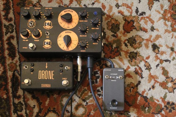
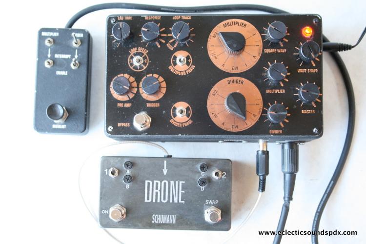
Hey, I am set on building a full PLL (witch drone and moment add-ons)

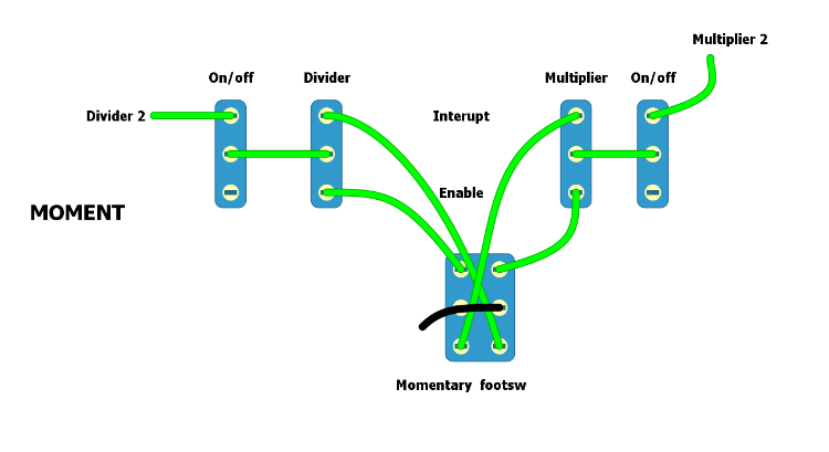
Now I'm stuck at the wiring of the "moment" switches. Here is the circuit as drawn in the schematic


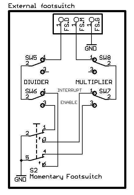
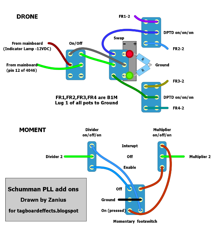
and here it is in diylc drawing


It case the switches are on/off/on, the "6" lug of each switch doesn't connect anything to anywhere. It could make sense if the switches were on/on/on though.

I can't seem to find that information online, has anyone read something about that?

Here is a link with schematics and layouts for the pll. http://www.aronnelson.com/gallery/main.php/v/digi2t/veros/Schumann+PLL/

Any input would be great :)
Reply | Threaded
Open this post in threaded view
|

Re: Switch schematic

Ciaran Haslett
Hi Zanius.

The divider and Multiplier switches are just DPDT On/On.  An on/OFF/on state would completely disconnect lugs 2 from all the other lugs but you can see that a connection is always required for SW6 and SW7.

Your wiring diagram is spot on.  Just be careful what way you have your momentary orientated before you start soldering or its operation will be backwards.
Reply | Threaded
Open this post in threaded view
|

Re: Switch schematic

Zanius
I think I got it wrong.
I was trying to interpratate the schematic according to this image


but now I see that image


So, I guess the schematic is based on that second picture, with 4 spdt switches and not 2 dpdt.
After all, that makes way more sense.


Now that raises another question. Why use 2 on/on for each function instead of using 1 on/off/on for each? Trying to look sophisticated maybe? lol
Reply | Threaded
Open this post in threaded view
|

Re: Switch schematic

Alex
That looks correct.
They are supposed to be 4 SPDTs.
If you want I've drawn a now verified layout a while back:
http://tagboardeffects.blogspot.fr/2015/11/schumann-pll.html
Reply | Threaded
Open this post in threaded view
|

Re: Switch schematic

Zanius
Yeah Alex, already built your vero and I am currently organizing things to get started for the final compilation.

About the switches, I am going to use a single on/off/on spdt, mostly because the box is all ready and I hate to re-drill it. I don't see any reason why that shouldn't work.
Reply | Threaded
Open this post in threaded view
|

Re: Switch schematic

Alex
2 SPDT On-Off-On would work.
Just connect FS.D to Sw6 - 2 and FS.M to Sw7 - 2.
Reply | Threaded
Open this post in threaded view
|

Re: Switch schematic

Zanius
Well, since I did it for my convenience, I might as well share it


I think that's correct. Notice that the connection for the LEDs on the board is taken by the negative side of the supply, so you have to connect them backwards.