TDA2030 amp

classic Classic list List threaded Threaded
9 messages Options
Reply | Threaded
Open this post in threaded view
|

TDA2030 amp

Stinger25
Hi,
I've tried to do a layout for TDA2030 amp, and would like to share and ask you guys to have a look and see if they can find any errors.
Also I'd like to know if there's a mod to get -9v/+9v from the bipolar daughter board that Mark posted few days ago.

Here's a link to the schematics:
http://www.generalguitargadgets.com/pdf/ggg_20x0_amp.pdf?phpMyAdmin=78482479fd7e7fc3768044a841b3e85a

Reply | Threaded
Open this post in threaded view
|

Re: TDA2030 amp

IvIark
Administrator
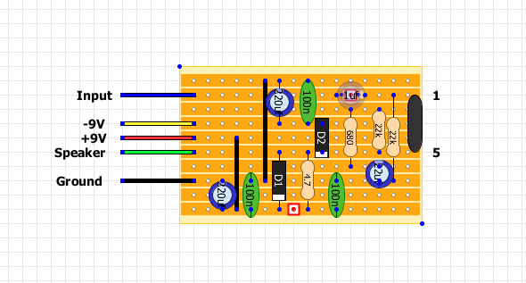
The layout appears to be ok after a quick once over.  The voltage converter layout I posted the other day is more complicated than you need.  Just use this one to give you the required -9V.

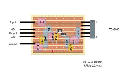
http://tagboardeffects.blogspot.co.uk/2012/05/negative-voltage-inverter.html

Also bear in mind that I don't think the pins of the TDA2030 have a 2.5mm pitch between consecutive pins like vero requires, so I think you'll have to spread the pins out a bit to get them in the required holes.  Not a biggie but something to bear in mind.
Reply | Threaded
Open this post in threaded view
|

Re: TDA2030 amp

Stinger25
Thanks, Mark,
I think i'll it this weekend if it'll be ok, i'll start to think about a pre amp
Reply | Threaded
Open this post in threaded view
|

Re: TDA2030 amp

Stinger25
I've built it, figured there is an error in the schematics I provided and pins 4 and 5 on the TDA2030 should be swapped.
The problem is, the damn thing doesn't work yet... Double checked the schematics, the layout, cuts, part numbers... Any ideas, guys?
Reply | Threaded
Open this post in threaded view
|

Re: TDA2030 amp

AC_FX
Thinking about building this - your layout looks good to me too.  One question for you - you haven't grounded the tab on the IC by heatsinking it, have you?  According to the datasheet, it's connected to Pin 3 which is V-
Reply | Threaded
Open this post in threaded view
|

Re: TDA2030 amp

AC_FX
Also. . . yes, you're right, the schematic from ggg is wrong, has pins 4 and 5 mis-labeled.  But their PCB layout is right.  So this layout either needs to have the IC pin connections swapped, or have those two rows switched around.  Still haven't built one - thinking I might just make a PCB instead of doing this on vero.  Bending those little legs on the IC makes me nervous.  I've broken them from handling them too much before, they're not very robust where they go into the body of the IC.
Reply | Threaded
Open this post in threaded view
|

Re: TDA2030 amp

Stinger25
No, I didn't grounded the heat sink.
I don't know...
Couldn't make the damn thing to work, no sound at all, just the heat sink heating...
Reply | Threaded
Open this post in threaded view
|

Re: TDA2030 amp

Senor Avocado
I was really interested in building this as well so i tried swapping the rows and did my own layout, this is my first one ever so please be patient! I was just wondering if this looks correct
Reply | Threaded
Open this post in threaded view
|

Re: TDA2030 amp

Senor Avocado