Testing before boxing
|
Testing before boxing, I've read this a few times on the forum. Surely I understand why you should do it, just can't figure out how. Do you solder all the wires outside the box, test it, and put it in? Doesn't sound too practical to me. Alligator clips maybe?
|
|
Administrator
|
Solder up the pots and then just connect the board input and output directly to the sockets using a terminal block like this:
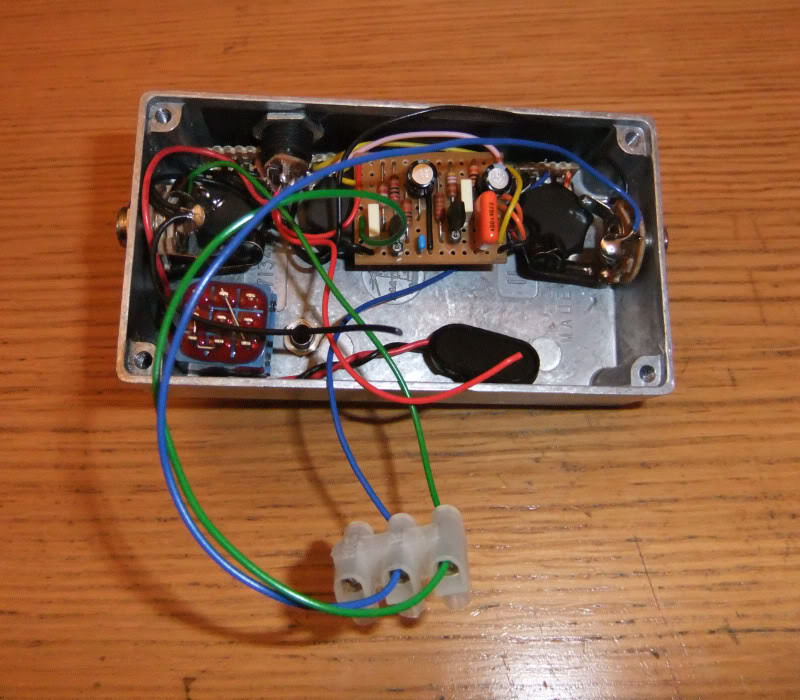 Yes I know that is actually boxed but it gives you an idea of what I mean  I always test the board on its own before mounting it in the box or else you have to take everything apart to debug, and definitely test before soldering the switch because otherwise you just add another potential point of failure. |
|
In reply to this post by imre
So actually you just bypass the switch with the terminal block, outside the box? And you have the dc jack and the pots & optional mode switches all soldered up already? So there's no way to test the board without the wires? Of course you need them, i know, but it doesn't sound that practical.
|
|
Administrator
|
I just posted the pic because it was the only one I'd taken using a terminal block. When I test the board before boxing I have the wires soldered up to the board and usually put the pots directly in a breadboard (pin type pots) and make the connection that way. Then I also attach a battery or power supply to a terminal block for the power and take all the ground connections to the negative terminal.
|
|
In reply to this post by imre
I think it's very practical for a couple of reasons. First, as lvlark already said, you're eliminating the switch as a potential point of failure if the event that you need to debug. But, more importantly for me is that this allows you to cheaply build and experiment with lots of different circuits without going to the trouble and expense of buying/painting/drilling/etc. enclosures for them all. Who's to say that his fuzz that you covet so much is going to work well with your personal gear? So, you build it, and if you like it, you box it. If you don't like it, you clip the pots, jacks, and dc jack off, salvage any components such as transistors or an ic that you can reuse, and move on to the next one. To me it's impractical to box up a circuit before you know whether it's going to work for YOU.
|
|
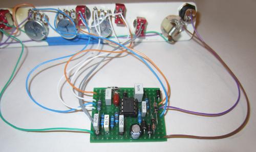
I just mount everything to a strip of pickguard material for testing.
|
|
In reply to this post by imre
I built one of these and its really helped get confidence with my building - works on this rig then it'll work in the box. Probably dont need the pot for varying the battery voltage - but with a little thought you can adapt this to meet your needs. Point being its much easier to debug prior to boxing.
http://beavisaudio.com/bboard/images/io_diy.jpg |
|
I have a little test box in a 1590A with in/out sockets, switch, power socket and led.
The 9v, GND, In and Out leads from there have clips on the end. When building boards, I build it up, wire up the pots and then just wires for the 9v, GND, In and Out leads - these connect in to the above clips for testing. When i'm done testing, it's working and I start boxing it, I just clip the 9v, GND, In and Out leads down to length for where they are going. Ian |
|
+1 for the above, exactly what I have done, work very nicely and saves sooooo much wasted time.
Thanks Dave |
|
In reply to this post by ichilton
Pretty much exactly what I do but I use a small solderless breadboard, I wired up the input/output and DC sockets and a dpdt switch so I can bypass the effect. This lets me daisychain a few boards which is nice if I'm lesting a dual effect build or if I'm just feeling lazy or don't have time to box many up I can still stack a few effects to see if they're worth it.
|
|
In reply to this post by imre
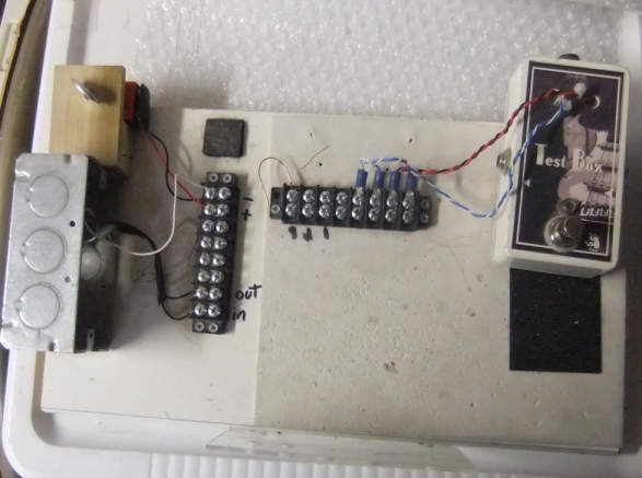 I figured I would post since I do it a bit different. Version 1 is on the left just two jack drilled into an electrical box I had laying around. No led no switch just screw your 4 wires in and test. Version 2 on the right I have a small plexiglass sheet attached to the front if I want to mount the pots but the only time I ever do is if I am modding a circuit and testing the sweep of the pots. |
|
In reply to this post by ichilton
ichilton or Dave, would it be possible to post a picture of your test box ?
Thanks |
|
In reply to this post by imre
I built myself a little testrig stomp box to make it easy. I just wire up the pots and make leads for in/out, 9v/ground, and then hook it up to this thing (I don't have a better picture, but the wires coming out of the front are alligator clips. The black wire coming out of the top is an audio probe (the other end is a dmm probe lead) that I made switchable, which lets me "listen in" on the circuit wherever I touch it to the board.
Inspired by: this thread at madbean 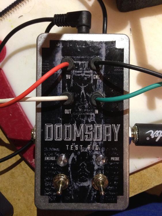 |
|
Ha, sorry, I missed Ian and Dave's posts - yeah, same idea.
|
|
Very cool, Todd! Mine is still on the breadboard but it works exactly like yours. I never have a box to spare, though...  |
|
Thanks Goran - yeah it was tough to sacrifice the box for it, but I figured, what the hell -- I'll put a cool label on it and at least it'll be nice to look at, lol.
|
|
Here's Cody Descenes take on the subject:
http://music.codydeschenes.com/?p=2136 http://music.codydeschenes.com/?p=2149 Some kind of all-in-one test box, just hope he's covering the making of the whole build in a post soon. |
|
In reply to this post by imre
I built a very simple one from an enclosure I had mis-drilled and then mis-drilled again (because I'm awesome).
I just got a cheap 4 connector speaker terminal thingy and screwed it to the side (after drilling some holes for it and lining those holes with electrical tape in case my drunken yeti-liek drilling skills were a tiny bit off (homie don't want no shorts). 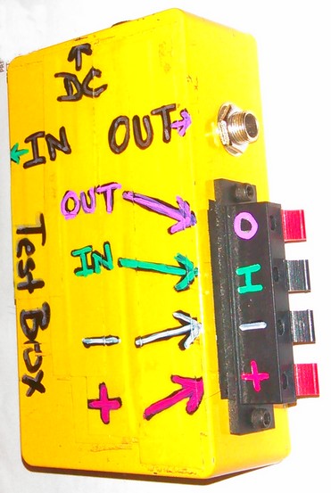 I always use Green wire for IN and Purple wire for OUT (just something I started doing to keep things straight in my head from circuit to circuit) so I color coded it with paint pens. I covered the top with electrical tape (yep, I happened to have yellow tape) so if I needed to set the boards on top of it, it would be insulated from short. Also, it covered all the wonky-ass holes I had previously drilled so I am not constantly reminded of my short-comings. It's wiring very simply. Red "+" terminal to + on DC jack, Black/White "-" terminal and IN/Out ground lugs to - on DC jack. The spring loaded terminals work very conveniently. I've got some 2 terminal ones as well that I might add for LEDs for circuits that have "built in" LED+/- but it's not terribly consequential. I've considered doing some kind of modular foot switch add on so I can use it with or without a footswitch (usually when I'm testing I just need to know it works, so switching is not an issue) but making it so that I can sort of "plug" the 3pdt in without soldering so that it's testing the switch as well, but can be easily removed fro the circuit. Again, would be cool, but mostly unnecessary. After seeing toddvirgil's picture, I think I want to add a toggle switch rather than plug, unplug, troubleshoot, plug, unplug, troubleshoot, plug, unplug etc. |
|
In reply to this post by imre
I finally broke down and made a testing station out of a Hammond enclosure and a breadboard, just to make things a little easier on myself when troubleshooting is required. The box has input and output jacks which connect to the blue and green wires you see in the middle of the breadboard. I stuck a standoff on there - I usually have a standoff hole in my boards, so this helps things stay put on the test box. For power there's a 2.1mm jack and a battery, wired in the usual switched manner. The binding posts on the outside aren't really necessary, but the black one comes in handy as a spot to put the negative probe of my multimeter when testing. I have a couple of ideas for dealing with pots and switches, but haven't decided which way to go yet. . .
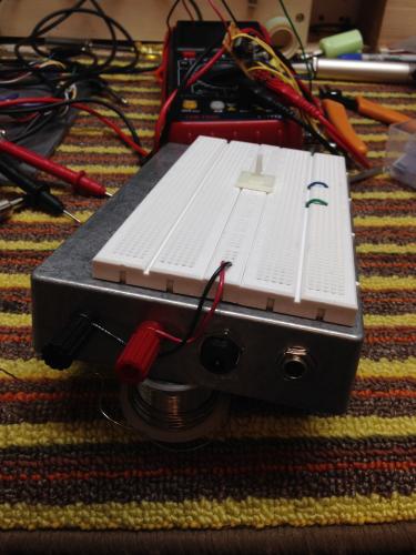 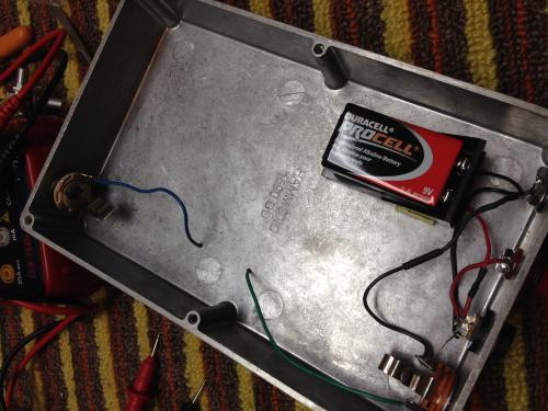 |
«
Return to Open Chat
|
1 view|%1 views
| Free forum by Nabble | Edit this page |

