The Gritty Kitty Boost
12
12
|
Administrator
|
Hey everyone, thanks to the help of a lot of people in the community I finally think I finished a pedal design I've been working on for a few months now, feels like years, but I need some help with creating the vero layout. I've been working with DIYLC, but I just haven't been able to visualize how to arrange it, so I was hoping someone with more experience could help me out, and possibly point my to some resources that show things step by step, like a video.
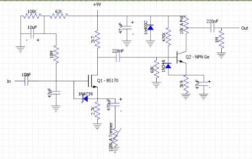
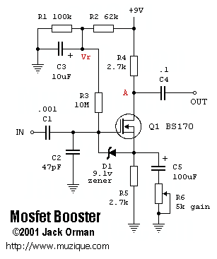
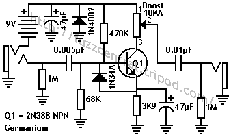
Here's the schematic I put together, not sure if I missed anything though  It's basically a combination of the AMZ Mosfet Booster  and Rangeblaster from Fuzz Central  There are still a few issues with values I need to deal with, but can't work with it on the breadboard anymore, it sounds really noisey. If some one can help with a working veroboard, I can get everything corrected and iron out all the details, and will be more than happy to put it all up for anyone that wants to put it together. |
|
This post was updated on .
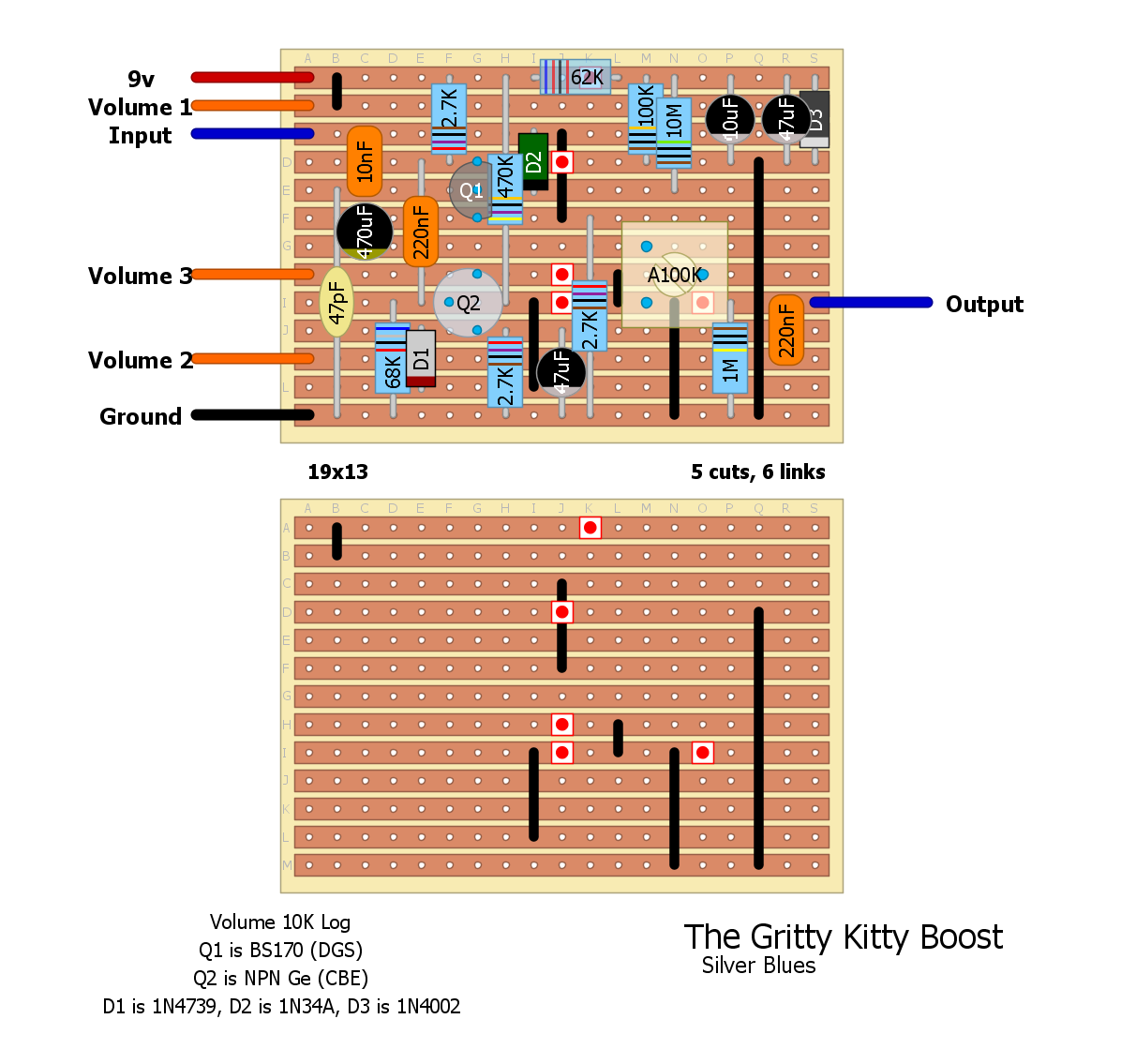
All right so I took a crack at it. Schematic is simple but you are certainly correct, it is hard to visualize
 Let me know if I've missed anything or if something's out of place. Let me know if I've missed anything or if something's out of place.

Through all the worry and pain we move on
|
|
Administrator
|
Awesome Silver. That was unbelievably fast. I'm looking at them both and I think its all there. What's the big difference between the two aside from the size, cuts, & links?
FYI, if anyone is looking at making this, just hold off a bit, I have to play with some of the values. It got way too noisey on the breadboard to really get a good idea of the sound, tone, etc. Once I get it all situated I'll post the changes, and sound clips. |
|
This post was updated on .
There's no real difference other than the ones you mentioned. I just thought the first one was too wide relative to the height so I tried to make it more space efficient. Both are functionally identical I hope.
EDIT Shoot, I did make a mistake with layout 1, good thing I did layout 2 because I pretty much would have had to do it that way to fix it. Second one should be all right. Too bad because I thought the first one was a little neater.
Through all the worry and pain we move on
|
|
Administrator
|
I didn't even notice a mistake with V1, but that makes it easier for me to work on this so I can give final values, and tune it.
 . Thanks again Silver so far for your help. . Thanks again Silver so far for your help.
|
|
No prob, and I'll offer more if needed. The mistake was with the arrangement of the resistors in the power section, the schematic clearly shows that the 2K7 and the 470K from the 'Rangemaster' half don't come after the 62K from the 'MOSFET' half - only the 100K/10uF parallel combo is to be affected by it and I had it so that the whole thing went through that 62K resistor. The other way it's more tight to the schem, and probably will work better.
Through all the worry and pain we move on
|
|
Administrator
|
Nice. I now know who to bother when I need help with layouts
 . BTW, how did you learn to make layouts? I really need to learn how if I'm going to be designing my own circuits.......and don't have to bother you about it all the time. lol . BTW, how did you learn to make layouts? I really need to learn how if I'm going to be designing my own circuits.......and don't have to bother you about it all the time. lol
|
|
Lol
 Well, I started by reading the layout guide here, and then just examined some existing layouts to see how things were connected. The way I think about it is that on a vero, everything is connected and you remove the connections you don't want. (That's not entirely true, because only each row is connected, but you know what I'm getting at.) I'm awful at explaining things, always have been lol, but I sure don't mind doing layouts as long as they aren't hyper-complicated. Questions, just ask. Well, I started by reading the layout guide here, and then just examined some existing layouts to see how things were connected. The way I think about it is that on a vero, everything is connected and you remove the connections you don't want. (That's not entirely true, because only each row is connected, but you know what I'm getting at.) I'm awful at explaining things, always have been lol, but I sure don't mind doing layouts as long as they aren't hyper-complicated. Questions, just ask.
Through all the worry and pain we move on
|
|
Administrator
|
Nice. I'll try to do that so I can get better. BTW, I just put this together using layout v2 and works really well. I did notice a few things though, the trimmer doesn't really seem to do anything, not sure if its something i did wrong, going to check it out tomorrow when I have more time. Also, there's a high pitch noise coming through when it's one. Not sure if that's because its picking something up while the back is open, or if there's a tiny bridge somewhere.
A few changes, the 68k that goes from the Base of Q2 to ground i changed to 56k, I also changed the 2.7k resistor from Emitter of Q2 to ground to 3.6k. I think it just made for better biasing, but still have to check. Also, the Ge transistor I used was a Russian MP38A. I played around with different hfe ranges, but they were all out the same from about 60hfe-100hfe, and settled on 94hfe with a leakage of about .35mA. I'll make a video soon as soon as I clean up the guts and close it. But I must say if it wasn't for you Silver, I wouldn't have been able to box it. So thanks  . .
|
|
Haha, that's great to hear man, you're very welcome. If those are the final component changes I'll modify and repost the layout.
As for the noise, what kind of power supply are you using? A lot of my pedals squeal because of my bad brick, that could be it.
Through all the worry and pain we move on
|
|
Administrator
|
Its a 9Spot adapter. I only really heard it while tweaking it with headphones on. I guess its my fault for using really good headphones. lol.
I might have to make some other changes. I turned up my amp and it sounds kinda farty, especially when multiple strings are hit. I'm not sure what the problem is yet, think it might be the bias resistors. Any idea what the reading should be from Collector - Emitter? I checked mine and got 9V, which seems really high. |
|
Not sure about collector-emitter, but typically you're looking for ~4.5v at the collector at proper bias. It depends on the circuit, thought, sometimes it's different. Like, my Hematoma preamp stage sits at like 1.8v at the drain but it sounds totally fine.
Through all the worry and pain we move on
|
|
Administrator
|
I'll play with the bias resistors and see what happens, it might be the problem.....I hope.....

|
|
Administrator
|
Solve the flatulence issue, it was down to biasing. I had to change the resistor to the left of D1 back to 68k, and the 2.7k resistor from Q2 to ground to 820ohm. Sounds much better, still trying to figure out why the trimmer isn't doing anything.
|
|
Nice. I thought it was a little odd to see that trimmer where it is, most of the time something like that would be before the cap. If you like, try removing the link that connects 2 and 3 and connect the ground straight to 2 and see if that helps.
Through all the worry and pain we move on
|
|
Administrator
|
I'll give that a try when I get home from work. Since the first stage is based on the amz MOSFET booster, the pot has lug 1
|
|
Any news on this one, Rocket?
Through all the worry and pain we move on
|
|
Administrator
|
Sorry for the delay Silver. Haven't had much time to work on it. Hopefully Tuesday I'll get some free time. Now the the biasing seems good, it sounds kinda muffled and overly dark. I'm thinking that the output cap from the first stage needs to be a lower value, cause there's too much treble being cut from the high pass filter (220nf cap, 68k to ground). You think that's the problem? According the the AMZ calculator it cuts anything over 106.4Hz.
BTW, I never thought I would ever say there's too much bass as a bass player. lol. |
 Funny, a high pass with a 220nF and a 68K would cut everything below about 10Hz, which is totally fine. Sometimes filters between stages can get too much bass through, so I think that may be it. The good thing is I don't see any traditional R/C low pass filters that could be too deep in your circuit. I ran into that problem with my Hematoma, the low setting on the EQ shift cuts at like 159Hz (a low pass!!!), which is ridiculous and unusable. (The high setting also cuts at 4825Hz which is WAY too high to notice any difference when the knob is tweaked.) I would start by trying some smaller coupling caps.
Through all the worry and pain we move on
|
|
Administrator
|
Finally got some time to work on this, so here are the changes to make it work better.
Change the resistor to the left of D1 to 68k, and the 2.7k resistor from Q2 to ground to 820ohm. Which may be different depending on the transistor you use, as they are for biasing. The 220nF cap between the two stages can be left alone or changed to suit the tone you want, I changed it to 1uF to get even more bass out of it. Finally, the link that connects 2 and 3 and connect 2 straight to ground. I'm sure there could be more tweaking done, so if anyone want to take a swing at it and mod it or whatever go for it, and let me know how it turns out. |
«
Return to Circuit designs
|
1 view|%1 views
| Free forum by Nabble | Edit this page |

