The Muffer

classic Classic list List threaded Threaded
14 messages Options
Reply | Threaded
Open this post in threaded view
|

The Muffer

rocket88
Administrator
This post was updated on .
Decided to try another layout.

From AMZ:
"A good single transistor design can do the job well. Let's just extract a section of the classic Big Muff, modify it slightly and use it as a single booster stage. It can provide over 30db of gain and will be fairly low noise.

If D1, D2 and C3 are not used, the circuit will amplify without distorting. This is useful in overdriving a tube amp input as a clean boost or providing a boost to a weak guitar signal. When the diodes and capacitor are added, the circuit will become a simple distortion box.

The transistor is not too critical. Use the 2N3904, 2N2484, 2N5088, BC108 or similar NPN silicon devices. When used as a distortion, the 10uF/C3 capacitor controls high content to some extent. Make it smaller to add some brightness or leave it as shown for full range. The diodes may be replaced with germanium types for a different clipping response though I would use 4 diodes (2 pairs) to keep the output volume at a higher level."

Layout:


Schematic
Reply | Threaded
Open this post in threaded view
|

Re: The Muffer

IvIark
Administrator
A couple of things need correcting.  

The Sw1 connection is at the base, not the input wire, so you can remove that link and move the Sw1 wire to the row below the input.

R2 goes from base to collector, not input to collector

The 10K resistor from 9V goes to the collector, you have it going to the other side of the cap

If you're including a current limiting resistor for the supply, the 9V wire should be on the other side of the 100R, otherwise you're only limiting current to the filter cap instead of to the circuit.
Reply | Threaded
Open this post in threaded view
|

Re: The Muffer

rocket88
Administrator
Damn. I'll make the changes when I get home.  I thought I had those one. I see the error in the current limiting resistor and the reversed cap. I think I did those after I exported the file to a png and forgot to re-export it. I think I got a little to excited and forgot.

The 10k I get I need to move to the other side of the output cap, and pull it down to the collector. I see how I'm thinking I can do it easily after moving the Sw1 down 2 rows.

I don't get why the switch (diodes), and r2 are placed wrong. I got from the schematic that one end of each of these components are essentially have one end connected to one side of the input cap which goes to the transistor Base. Like the signal enters the input cap gets split to the clipping diodes, r2 to collector, r1 to ground, and to Base. So I thought everything was tied to the input cap, which connects to both collector and base.
Reply | Threaded
Open this post in threaded view
|

Re: The Muffer

IvIark
Administrator
You have the diodes and 470K resistor linked at the wrong side of the input cap.  You have it linked to the input wire which is the line from the top left hand lug of the stomp switch.  They are both actually connected to the base which is the other side of the 1u input capacitor.

Remember what I was saying about thinking about the connections carefully.  If you look at the base of the transistor and follow the line you can see that the base should have 4 things connected to it.  The right hand side of the input cap, the diodes, the 100K resistor and the 470K resistor.  Its those connections that you should be looking out for when checking your layout.  If a point doesn't have the right number of connections then you know something is wrong somewhere.
Reply | Threaded
Open this post in threaded view
|

Re: The Muffer

rocket88
Administrator
It's funny I was going to ask before it that was the problem, because the more I looked are the schematic and layout that's what I thought I did wrong. I think the problem is that I need to keep what you said in mind and that the circuit, and think about it as a road rather than water, like what some of the electrical engineering books I have say, since water really doesn't care about order when flowing through pipes. So on that note, I have to not drive through people's yards.
Reply | Threaded
Open this post in threaded view
|

Re: The Muffer

rocket88
Administrator
This post was updated on .
Corrected Layout. I was also able to make it a little smaller, and I added a 1M pulldown resistor at the input to help prevent popping when switching.
Reply | Threaded
Open this post in threaded view
|

Re: The Muffer

IvIark
Administrator
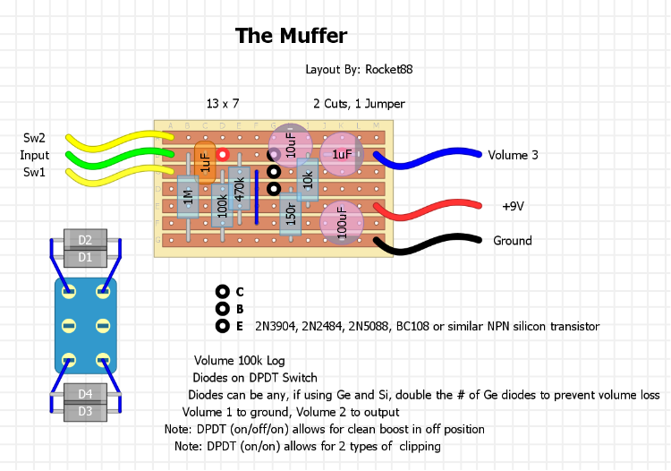
Still not quite there.  The 10K from supply is connected to the wrong side of the 10uF cap, it needs to be connected to the collector and so the positive side of that cap, not the negative.

Again look at the schematic and look at what is connected to the right hand side of the diodes.  Just the negative side of the 10u, and yet in this the Sw2 connection has the negative side of the 10u and one side of the 10K on the same row.

Easy fix, forget about the 100R resistor and move the 100K resistor so it goes from column I row B to column I row E, and that will do the trick.  

Plus you really need to add an extra columns or those wires on the right will have nothing to connect to  although if you remove the 100R entirely then that should leave space for those connections.

Everything else looks fine
Reply | Threaded
Open this post in threaded view
|

Re: The Muffer

rocket88
Administrator
Hahaha, I can't believe I forgot to leave a row for the connections in that one, I have no idea where my brain went.  
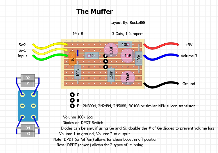
I made the changes, and removed the 100r, and I assume you meant to move the 10k to I/B to I/E, not the 100k on the left side of the layout. How come the 100r resistor isn't needed for power filtering? Also, next layout I'm hoping for the  you're good. Although I'm not sure if anyone checked the muff master layout. lol

Corrected Layout:
Reply | Threaded
Open this post in threaded view
|

Re: The Muffer

IvIark
Administrator
Yes 10K, see even I fuck up all the time
And I've checked it, go and have a look
Reply | Threaded
Open this post in threaded view
|

Re: The Muffer

rocket88
Administrator
Awesome, thanks buddy. This should be a nice small, simple boost that can get nice and dirty if you want it to. Now only if I can get it into a tiny 1590A, will be perfect.
Reply | Threaded
Open this post in threaded view
|

Re: The Muffer

piltdownman
Just a question: D3 and D4 are supposed to be oriented the same. right?  Thanks
Keith
Reply | Threaded
Open this post in threaded view
|

Re: The Muffer

rocket88
Administrator
D3 and D4 can be how ever and what ever you want them to be. I added a clipping diode selector switch so you can have options. On mine, I'm going to make one side asymmetrical silicon, and the other germanium. So on mine to prevent the germanium diodes from causing too much volume loss I'm going to have 4 ge diodes compared to 2 silicon on the other side. If you use an on-off-on switch in the off position you'll get a "clean" boost, since both sets of clipping diodes will be out of the circuit.
Reply | Threaded
Open this post in threaded view
|

Re: The Muffer

piltdownman
Got it.  Thanks
Keith
Reply | Threaded
Open this post in threaded view
|

Re: The Muffer

rocket88
Administrator