Tim off board wiring help!!!!

classic Classic list List threaded Threaded
15 messages Options
Reply | Threaded
Open this post in threaded view
|

Tim off board wiring help!!!!

brandon.a
Me again, sorry guys!! Circuit done, ready wire up. Ive havent wired up an effect with a built in boost before. Is this the wiring schematic I should use? !Offboard_Wiring_with_switchable_pre-effect_booster.png
Reply | Threaded
Open this post in threaded view
|

Re: Tim off board wiring help!!!!

nocentelli
Just follow the wiring instructions on the vero layout: it is not a 3PDT bypass like the input boost layout you linked. The Tim has a simple make/break SPDT switch that brings in another path to ground with a lower resistance and variable low end boost from the inverting input in parallel with the bass pot. Schematic is here, but is grotty quality

http://www.freestompboxes.org/viewtopic.php?f=7&t=2826&p=244804&hilit=Cochrane+tim#p244804
Reply | Threaded
Open this post in threaded view
|

Re: Tim off board wiring help!!!!

brandon.a
It wouldnt let me view the image?? How can it not be a 3pdt?? Shouldnt there be an led on that switch?? Sorry, total noob here. Thought this one wouldnt be too bad. If you can screen shot the image that you see and post it that would be awesome
Reply | Threaded
Open this post in threaded view
|

Re: Tim off board wiring help!!!!

nocentelli
brandon.a wrote
How can it not be a 3pdt?? Shouldnt there be an led on that switch??
The 3PDT on the left hand-side of the "offboard wiring with switchable pre-boost" you linked is used because it supposes you are building a circuit (e.g. overdrive) AND an entirely separate boost circuit that you only want to engage/disengage if the main effect OD is engaged.

The right-hand 3PDT bypasses both of the circuits, and if it is engaged/un-bypassed you can also engage a separate booster circuit with the left-hand 3PDT which comes before the main OD.

In the Tim, the booster circuit is simply an extra cap (150n), extra resistor and two pots (boost and boost tone) that are switched in to the main Tim circuit with a single make/break connection that boosts the gain by an amount pre-set by the pots. If you wanted an LED, you would need a DPDT and use the second pole for the boost LED indicator. This is all spelled out on IvIark's vero layout, though I admit the instructions might not be totally clear: "Boost switch SP (single pole) or DP (double pole) for LED indication"


Here is the schematic, with the boost circuit highlighted in a green rectangle, and the boost switch in the red circle. The second pole of the boost switch that does the LED is not shown. The original schematic has been removed from FSB/the whole internet, so this is a very lo-res screen grab of the picture preview from whatever hosting site was used by the OP, with my MS paint modifications:


If you remove the the circuit in the green rectangle and the switch, you have a Timmy.

I'd advise registering with freestompboxes.org, this allows you to access a huge number of schematics of guitar pedals and is the source of the vast majority of schematics used to make layouts here at tagboardfx
Reply | Threaded
Open this post in threaded view
|

Re: Tim off board wiring help!!!!

motterpaul
I used a Tim for years in my effects loop of a two-channel Marshall to boost my higher gain leads.

It is a two effects in one box pedal - boost and gain. I used to have a little gain all the time. and use the Boost to make my guitar louder for lead solos.

To me, this is what a Tim is for, on its own it is not much of an overdrive for a clean amp, but it really puts dirtier amps over the top.

I would use this scheme: (and yes, both sides get an LED).

Reply | Threaded
Open this post in threaded view
|

Re: Tim off board wiring help!!!!

induction
Sorry to disagree, Paul. There's only one circuit in the Tim. The switching you posted is for two separate circuits, so it won't work.

Re-read the post directly above yours.
Reply | Threaded
Open this post in threaded view
|

Re: Tim off board wiring help!!!!

motterpaul
No need to apologize, but I know MY TIM pedal was a dual pedal with two 3pdt stomp switches, separate LEDs and a separate boost and gain section.

Maybe it is all on one circuit board, but if not, like most dual overdrives, you need separate stomp switches.

<nabble_embed>https://www.youtube.com/watch?v=qYX67cuxRS8</nabble_embed>


The "Timmy" is a singular pedal (just the boost, I believe, I never had one). I don't know this to be a fact, but my understanding was that the Timmy is a the separate boost section of the Tim, and the Tim was the overdrive section. I could have it backwards, but that is what I heard someplace.
Reply | Threaded
Open this post in threaded view
|

Re: Tim off board wiring help!!!!

induction
There's no need to rely on what you heard somewhere, especially since it isn't accurate. The schematic is printed just a few posts up, and was accurately described by Nocentelli. The correct wiring of the boost switch is printed in the layout in the same post.

The Timmy and the Tim are nearly identical circuits. The Tim is a 'dual pedal' only in that there are two stomp switches and two led's, but there are not separate boost and gain 'sections'. (Did you ever try to turn the boost on with the overdrive in bypass? It doesn't work because the boost is not a separate circuit.) The boost switch just adds in a few extra passive components around the first op-amp to increase the gain. With the boost off, the circuit is identical to the Timmy, except the gain pot is a smaller value, and of course there's the effects loop*.

Yes, the boost switch is a stomp switch, and yes the boost switch can control an led. But the wiring you posted will not work, and the OP should not use it. The boost switch can be a 3PDT, but only a DPST is required (5 of the 9 lugs of the 3PDT will be unused), and it will not be wired like two individual standard bypass switches in series. I don't mean to be insistent about it, but I want to make sure we're giving the OP accurate instructions.

* BTW: The effects loop is functionally identical to just putting the loop effects directly after the Tim, except that the loop effects will all be bypassed whenever the Tim is bypassed. If you have a bunch of pedals you want to switch on only for solos, the effects loop saves you from having to activate/bypass them all individually, but it doesn't insert them into the Tim circuit, it just puts them after it.
Reply | Threaded
Open this post in threaded view
|

Re: Tim off board wiring help!!!!

Chris60601
OMG! You killed Timmy.... I mean.... Well, yanno what I mean
Yeah, 220, 221. Whatever it takes.
Reply | Threaded
Open this post in threaded view
|

Re: Tim off board wiring help!!!!

Chris60601
In reply to this post by motterpaul
Very odd - I never really seen a Tim. It's not really what I expected. Honestly, I don't know what I expected.
Yeah, 220, 221. Whatever it takes.
Reply | Threaded
Open this post in threaded view
|

Re: Tim off board wiring help!!!!

motterpaul
This post was updated on .
In reply to this post by induction
Mine did work that way - boost separate from "bypass".

Actually, I was just looking at pictures and I had one of the early hand-wired ones where the right side was labeled "ON' - not "bypass."

I essentially used my Tim with the Boost on all the time (LED on) and with the bypass also "off" (LED off) until I wanted a boost for a solo, and then I would hit "bypass" and the LED would come on, as well as the added volume.  If the boost was ever accidentally turned off (LED off) I would hear the loss of tone even when the "Bypass" switch was (LED) off.

Maybe mine was modded, I don't know because it was acquired before I started building pedals, but mine was a true dual overdrive where both circuits worked separately.

Also - I think it is pretty well-known that the TIM went through a few different versions over the years.
Reply | Threaded
Open this post in threaded view
|

Re: Tim off board wiring help!!!!

nocentelli
We have no way of knowing how early Tims were wired, since there are no schematics or layouts on the net.

I assumed OP was referring to the Tim layout hosted here at tagboardfx which requires only a DPDT for boost with LED.
Reply | Threaded
Open this post in threaded view
|

Re: Tim off board wiring help!!!!

motterpaul
This post was updated on .
Yeah - I have been googling around today and could find very little about the original Tims. Not even a manual.

From what I can tell (by asking in another forum) - my Tim was different. It just goes to show one can't always rely on personal experience.
Reply | Threaded
Open this post in threaded view
|

Re: Tim off board wiring help!!!!

induction
In reply to this post by motterpaul
Hi Paul. I'm guessing that either yours was modded or counterfeit, or you're misremembering. The different versions of the Tim did not use different circuits. Beyond the change from perf to pcb, the different versions just had differences in the number of clipping diodes, and in the types of switches used for selecting the diodes. If yours had a boost section that worked independently of the overdrive, then it was different from every other Tim I've encountered, either in real life or on the internet.

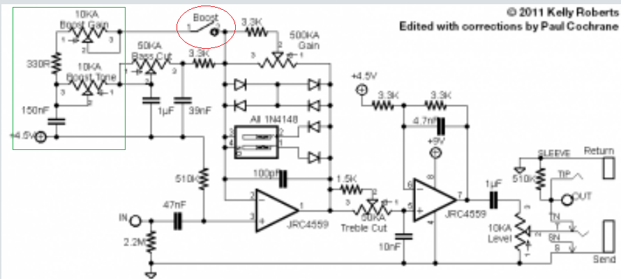
Paul Cochrane, the designer of the Tim and the Timmy describes both the circuit and it's design history here. He description is consistent with the previous ones in this discussion by Nocentelli and myself.

A few posts later in the thread, he corrects someone who wants to build 'the boost side' into a stand-alone pedal:
Paul Cochrane wrote
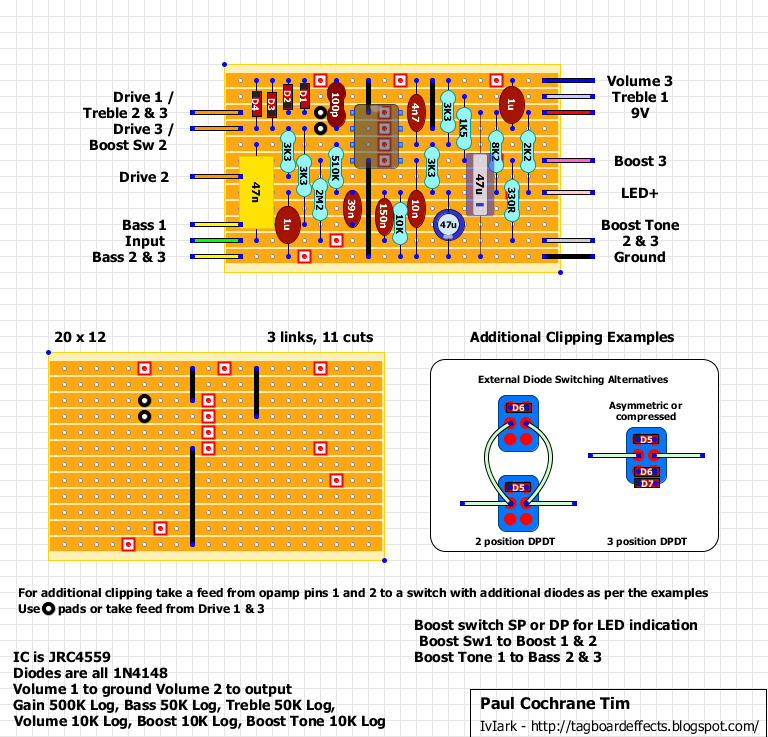
The boost section is laid out in the last section above. It's all there.

I don't think it's going to work for you though. It's a gain boost for the clipper circuit. It's not the same as a stand alone boost slamming into something. That would increase the signal level going into a pedal instead of increasing it's gain. The boost mode is part of the clipper.
Even later in the thread, he states that the difference between the newer versions and the early ones was that the clipping switch on the early ones was a pull-switch on the boost volume pot instead of a stomp switch.

I assume if there were alternate versions with a stand-alone boost, he would have mentioned it there instead of flatly contradicting the idea.

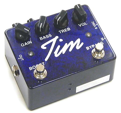
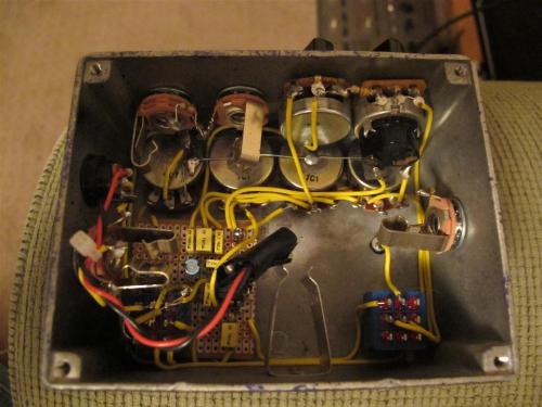
Here's an image of an early Tim (perf board and pull-pot clipping switch). Notice there's only one board, and the boost switch only uses 4 of the 9 lugs.


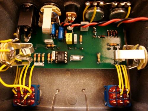
Here's an image of a later Tim (pcb and no pull-pot). Count the unused lugs on the boost switch.


I can see I've become pedantic now. I get carried away sometimes. I hope I don't sound too argumentative; the internet can be funny that way. Anyway, I agree it's a great overdrive.

Paul, you mentioned you had pictures of yours. Are you willing to post them? I'm sure I'm not the only one who'd like to see them. Any chance of gutshots?
Reply | Threaded
Open this post in threaded view
|

Re: Tim off board wiring help!!!!

motterpaul
No worries. I do know I am not crazy, so the only thing I can think of is that mine was modded somehow. Things happen when you buy off of Craigs list.  My neighbor still has it so I can probably get a look at it if we can get it off the pedal board.