Tokai Metal Driver (TMD-1)
|
Well, I asked for this in the Requests and decided to do a layout myself.
 This is from the schematic at FSB (see my Request thread). I made one change from the original schematic - substituted a 1 uF cap after the tone stage versus the 47 uF cap. Also, I tried both LF353 and NE5532 ICs and liked the NE5532 best. Of course, you can use any pin-compatible dual op amp you have. This is from the schematic at FSB (see my Request thread). I made one change from the original schematic - substituted a 1 uF cap after the tone stage versus the 47 uF cap. Also, I tried both LF353 and NE5532 ICs and liked the NE5532 best. Of course, you can use any pin-compatible dual op amp you have.
Here's the layout... 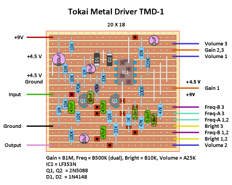 The layout is confirmed. I built it over the last couple of days after getting the 500K dual pot and some 5.6 nF caps from Smallbear Electronics. Here's my vero... 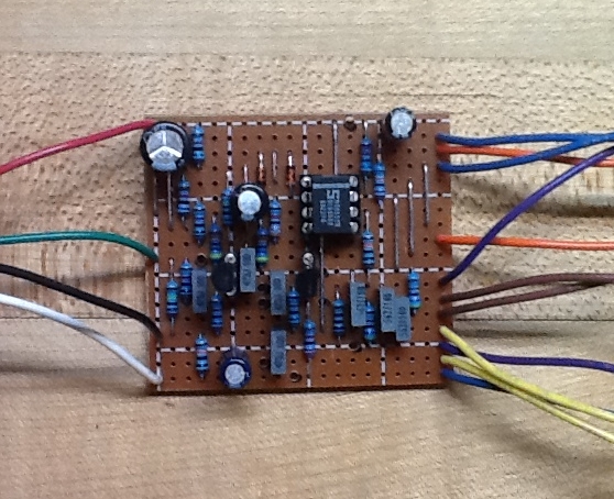 Some comments after testing. This is a cool effect with a unique tone circuit which can provide a range of tones similar to a wah. You can go from liquid "woman" tone to a crispy, thin tone by adjusting the Freq and Bright knobs. The A1M pot gives a good range of gain, well into the distortion range - but NOT what I would consider metal! Still, some nice distorted rock tones can be had. However, I'm not entirely happy with the distortion. It seems a bit "flabby" and "sputtery" at times, perhaps due to the simple two 1N4148 diode clipper in the first op amp feedback loop. Note this is an inverting stage, so the diodes are hard clipping. Now, I discovered that the circuit is very similar to the Xotic AC Booster in this regard (inverting op amp gain stage with diode clipping), and it supposedly uses asymmetric diodes and (by all accounts) gets a good tone. In fact, I may instead try replacing the diodes with LEDs to see if it improves the distortion. Certainly a lot of possibilities... Anyhow, have fun with this, and if you build it, let me know if try any mods.  |
|
Administrator
|
Nice one Frank

|
|
Administrator
|
I just checked this out for a video on YouTube, it's pretty unique, I'm going to have to add this to the build list. I expected something higher gain, and wahish, but definitely not what I expected, but really cool 80's awesomeness.
|
|
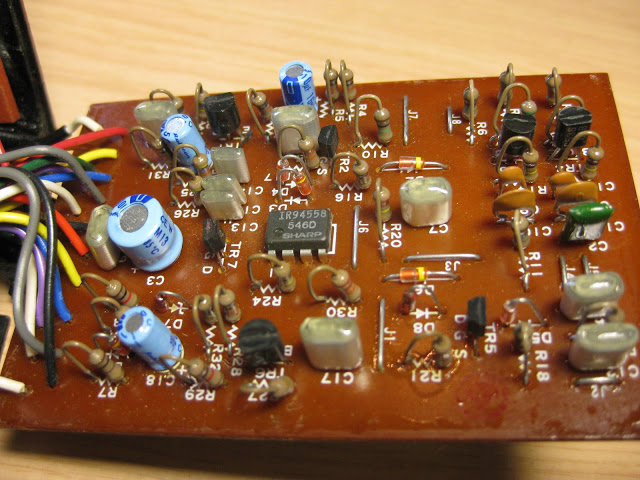
Yeah, there are hardly any YouTube videos for this, but from my research it appears to be highly regarded among Tokai effects collectors. There are some images on the web of the actual effect's circuit board - see below (a couple on Mirosol's blog), and they show what appear to be some JFETs. I thought those may be part of a buffer/switching circuit, but I don't know. Everything else looks consistent with the schematic. In any case, I'll probably mod mine with some LED clippers and report back what I find.
|
|
OK - I replaced the 1N4148 clipping diodes with LEDs and now the TMD sounds GREAT!
 I used some 3mm amber LEDs I had sitting around, but I would probably go with red LEDs if you have those. I used some 3mm amber LEDs I had sitting around, but I would probably go with red LEDs if you have those.
I'll definitely box this one now - it's very versatile and can provide a range of sounds from mild overdrive to distortion, modulated by the unique tone filter. One experiment I will try while I have it set up on my test rig is to use separate 500K filter pots versus the dual. There may be some additional sounds available by setting those pots differently -- we'll see. 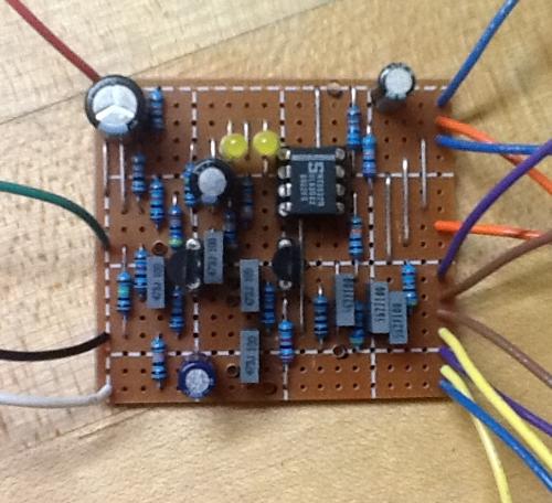
|
|
Thanks for the circuit Frank - it is on my list so I can have a bit play with it.
I would certainly agree that the TMD is a cracking pedal - I have one  It sounds great in front of a tube amp (aka Tubescreamer) used as a dirty booster. I found it to give a nice rock sound, but it is not a metal (as we now know it) pedal, I used the HM2 for the more dirty sounds. |
|
This post was updated on .
I ready to box mine up and will take a few pictures as I go. This will be interesting as it has the dual gang pot for Frequency, so I'll need to make sure the board fits over the pots properly. It should work fine in a 125B enclosure with four knobs. AS I mentioned above, the tone variation you get with the Frequency and Brightness controls is pretty cool! If this were on a breadboard, I would experiment with different cap and resistors values to see what the possibilities were. It's fine as is, though.
dbat69 - if you have an original, can you check the original diodes? In the image above, they appear to be silicon small signal types, but I'm wondering if they are different and have a higher forward voltage. The LEDs really changed the sound dramatically - for the better - when I switched them for my original 1N4148s. By the way - here is the updated vero. Enjoy! 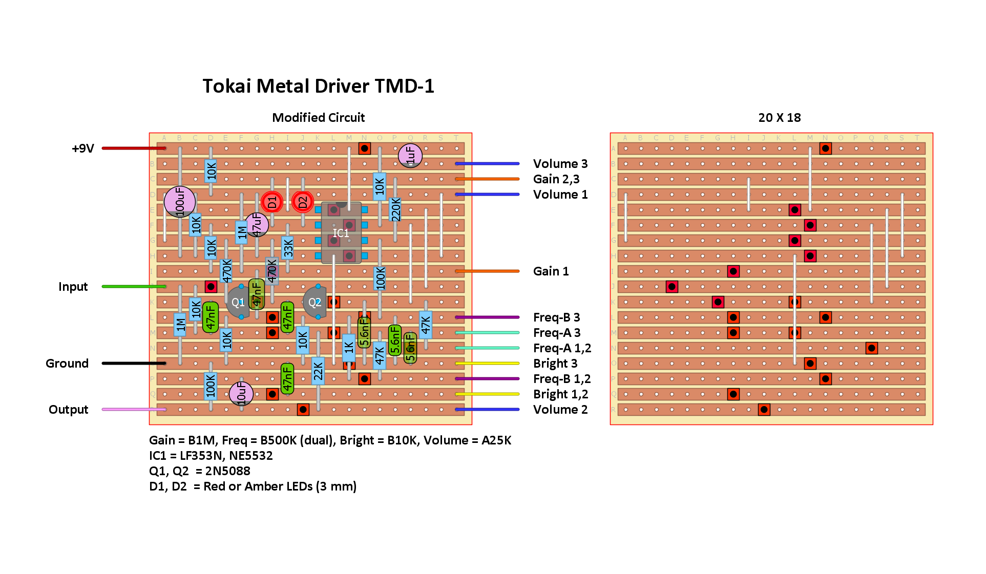
|
|
Frank, I'll have a look in a day or so when I get a moment (and find it first
 ) then I'll crack it open ) then I'll crack it open
If there is anything else you need to know while I have it open, just say and I'll see what I can find out. Now ... where is my hammer 
|
|
In reply to this post by Frank_NH
Frank There are 7 diodes and a zener. All the diodes look identical, small glass with a yellow band. They are smaller than Ge diodes and look about the size of schottkeys. They will be a version of something .. made in Japan The voltage drop for the various diodes on my meter reads between 588mV and 596mV. D3 and D4 which I presume are the clipping pair read 591mV and 593mV Hope this helps 
|
|
Thanks. It's hard to know unless there are markings on the diode body itself. 600 mV forward voltage is about the range of small signal Si diodes (1n4148s). If you want to experiment, you can put in a socket for the diodes and try out different kinds. I liked the LEDs enough just to solder them into my build.
If you notice anything about the layout that is inconsistent with you PCB let me know. If you can take some quick photos that would be great! 
|
|
Frank
My apologies, I forgot all about sending these - not sure if they are any help now, but here goes 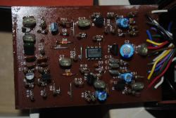 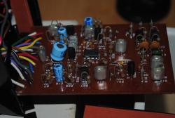 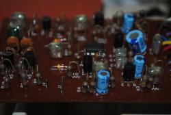 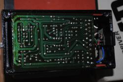
|
|
Built this using red 3mm LEDs and its really good. Definitely not metal though. Fantastic tone control. Cheers for the layout Frank
"Red velvet lines the black box"
|
«
Return to Booster, OD, Fuzz, Distortion
|
1 view|%1 views
| Free forum by Nabble | Edit this page |

