ToneGod Punisher

classic Classic list List threaded Threaded
7 messages Options
Reply | Threaded
Open this post in threaded view
|

ToneGod Punisher

wunderspud
Hi,

This is a cool little project... "The Punisher is a dynamic power supply sag simulator. The Punisher is not an audio effect but a companion effect that is to be used to control another effect to provide new sounds. You plug your audio signal and power supply into Punisher in series and connect the output audio signal and power supply into the effect to be controlled."

http://www.thetonegod.com/tech/punisher/punisher.html

That webpage has the schematics for two options - either the PSU voltage or the current can be modulated. I think with a DPDT it should be possible to switch between the two options. Perhaps.
Reply | Threaded
Open this post in threaded view
|

Re: ToneGod Punisher

boratto
Well, this is the 3rd vero on my life, so it must have a lot of mistakes... but maybe it can be a start, for guys here on community.


Reply | Threaded
Open this post in threaded view
|

Re: ToneGod Punisher

Neil mcNasty
Here's what I've found:
- The 1k at input should connect to pin 3, not pin 4.
- None of the IC 's get any power or ground. Connect +9v to pin 8 and Ground to pin 4 (this is standard for most common dual-opamps and is often excluded from the schematic, expecting everyone to allready know, or check the datasheet.
- The 2.2 meg resistor should connect between pin 1&2
- D2 and the 100R should not connect via the +9v rail, move the bottom leads of both up one row and insert a trace-cut on the left side of the 100R.
- The voltage output lead is missing.

I guess you will need to rearrange the layout quite a bit, so you might want to consider doing it from scratch since it quite easy to loose track when doing many changes.
I would also recomend to use DIYLC's standard LED and Trimmer symbols on the layout. I had too look twice before I figured out that those were trimmers...
Reply | Threaded
Open this post in threaded view
|

Re: ToneGod Punisher

boratto
Thank you Neil,
before start a new one i did some tweaks (the last chance).. lol.. now  i´m gonna take some aspirinas, it´s too much for my brains.


Reply | Threaded
Open this post in threaded view
|

Re: ToneGod Punisher

glasspak73
has anyone tried this one yet?
Reply | Threaded
Open this post in threaded view
|

Re: ToneGod Punisher

Freppo
In reply to this post by boratto
Hi Boratto
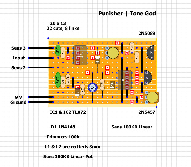
That's a nice try for a first layout
You should have seen my early attempts..

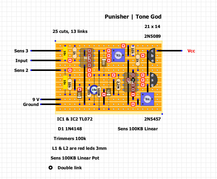
There are still a few problems though.

* IC2 needs +9v to pin 8 insted of pin 7
- just move up the double link one row

* The 10K resistor that goes to the negative input of the second op amp stage goes nowhere now
- it needs to go to op amp 2 pin 2. Just move down the top leg of the 10K resistor one row.

* You can remove the link next to the 10K resistor. It doesn't lead anywhere.

* The red LED that goes from the output of op amp stage two (pin 1) isn't connected
- you need to move the cut and link one column to the left so you can put L2 one row to the right

* D1  should connect to the trimmer R3, not to +9v.
- you need to rearrange a bit to move the cut to the other side of the diode

* The 10K resister from R3 isn't connected to the 2N5089
- you need to move the cut next to the 5089 a couple of colums to the left, and move the link to the right so it connects to the transistor

* The VCC connection (power out I guess you refer to) should come from 2N5457, not the 2N5089
- just move the connection down to the middle pin of the 2N5457

* The small link next to the R4 trimmer isn't really needed and can be removed

With these problems fixed you should have a working layout. :)

I hope that helps. However, maybe you should consider starting from scratch,
because using two TL072, the unused halves should ideally be decoupled.
Better yet, why not use just one TL072, insted of two halves of two dual op amps.
The schematic op amps each symbolize one halv of a single chip.

cheers / Fredrik
check out my building blog at www.parasitstudio.se
Reply | Threaded
Open this post in threaded view
|

Re: ToneGod Punisher

Freppo
Hmm.. Looking at the schematic I don't think any layout will work.
The schematic seem to be missing voltage reference for the first op amp stage.
I'm not sure, not I can't see how it can work otherwise...

I'll try it on the breadboard
check out my building blog at www.parasitstudio.se