Top Gear Fuzz Sustain
12
12
|
Just read the blurb you posted with your layout.."Totally unique circuitry" haha. OK they came up with the diodes in the feedback loop before the TS but they clearly lifted the BMP tonestack. Incidentally, I wonder how loud this circuit is? Even the TS needs a recovery stage. I saw one vid on youtube where the fella has the volume pinned but he doesn't bypass the pedal so you can't tell how it compared to dry volume.
|
|
Administrator
|
This post was updated on .
hey ciaran. just took a look at what you got and what i got. i'm still getting something different when i retrace that part. i'm going to wait, get my mind off it for a bit, and hit it again and see if i'm missing something. it does make more sense that the tonestack would be like a BMP, so i could be off.
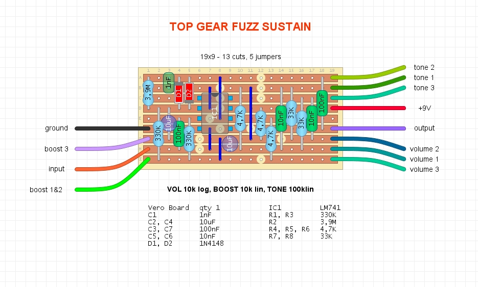
i just checked the layout too, and i posted one of my edits while i was moving stuff around, and must have forgot to save it  . i reposted the layout with the tonestack changed to a BMP type, and volume pot as you have it in your schematic. . i reposted the layout with the tonestack changed to a BMP type, and volume pot as you have it in your schematic.
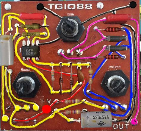
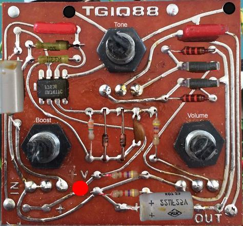
eh, its still kinda unique for the time. i mean we've all talked about how pretty much all pedals fall into 4 types of circuits. here's the board i was working with and i just went back and color coded the traces.  not color coded  from what i see Volume 1 is connected to +9V through a 4.7k resistor, not ground. the tonestack seems to have a 10nF cap to tone 1 and a 10nF cap to tone lug 2, and a criss cross of 33k resistors between from the front of one 10nF cap to the rear of the other. it also looks like to me that volume 2 goes to one of the 10nF caps, and volume 3 is connected to the other 10nF cap, as well as the 3.9M resistor from Pin 6 of the IC. maybe i'm missing something on this one. |
|
Those 2 resistors at the bottom are forming Vref....V+ > R1 > R2 >GND and Vol 1 is connected at the junction...so Vref. I should have labelled my wee arrows sorry
 . When doing this I always look for 2 resistors of the same value from v+ to GND first. Having no reference point like this makes tracing very difficult...loads of components seeming connecting all over the shop on a schematic . When doing this I always look for 2 resistors of the same value from v+ to GND first. Having no reference point like this makes tracing very difficult...loads of components seeming connecting all over the shop on a schematic The cap on Tone 2 is definitely the Output cap (purple trace) Tone 1 has a cap to Vol 1 (Vref) and a restore from the out of Vol 2 Tone 3 has a cap from Vol 2 output AND a resistor to Vol 1 (Vref again) It's definitely BMP. Vol 2 does go to one of the cap...and that goes to Tone 3 forming the High Pass side Vol 3 isn't connected to any cap. Only the resistor coming off Pin 6 (as shown in your pics) Your colour trace is spot on. I think the confusion was just with identifying Vref. It's the long yellow trace going from Vol 1, all the way round to Boost 1+2 and all the way to the top 2 resistors. But hey....between us we just saved someone the cost of a weeks holiday in Magaluf 
|
|
Administrator
|
agreed. what matters is we have a good schematic and layout. i'll still make one with a gainstage after the tonestack, maybe an lpb booster with trimmer to control the output. some times it takes more then one set of eyes to get it all right. good job all around.

|
|
Hello,
I made a layout (it's a bit more compact than the one posted on tagboardfx). It's verified (I built it and it works). I suggest to put a booster after the circuit, because it doesn't sou  nd very loud. nd very loud.
|
|
Administrator
|
Great job on that layout. Thanks for sharing!
|
|
You're welcome ;)
I didn't do much, all the kudos are for the original layout : I just made it slightly more compact. I have added a LPB after it, as the effect wasn't very loud. To be honnest, imho, it sounds ok but nothing like the asked price on Ebay or Reverb. The TONE is very efficient. I also like the way treble increase when you increase the BOOST, a bit like a MXR Dist+. |
«
Return to Open Chat
|
1 view|%1 views
| Free forum by Nabble | Edit this page |

