Total noob's First project - Meathead drawn by IvIark

classic Classic list List threaded Threaded
4 messages Options
Reply | Threaded
Open this post in threaded view
|

Total noob's First project - Meathead drawn by IvIark

Gabi Smith
This post was updated on .
Hello everybody,

First time here   Nice to meet you :-).

I'm totally beginner in electronic.

The curiusity make me try to do a clone of the dam meathed (that seems to be the easiest project).

In the shop of my city, they made little changes that will, i think, have concequences on the sound, but not on the experience :

- a bc546c instead of the bc182l
- The C5 film capacitor is the same than the c6 film capacitor but the value (in the schematic the 47uf isn't the same than the 10u)
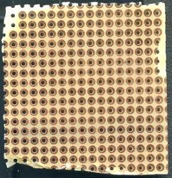
- and more frightening for me is a "kb" circuit board instead of a "z" one. Does it matter ?

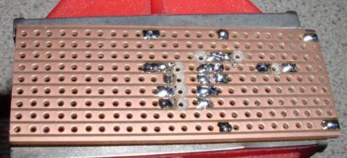
I've soldering everything on the board, but don't understand how the componements are connected between them to conduct the signal. So would it be possible to have a pic of the soldering face of this to see how it is supposed to looks like?

Thank you mate :-D

Gabi

edit : I'm totally new to this, so i don't know. My feeling is just that in the layout, you use a base that is conductive by line, like river, and I think the base i've got need to be connected with litle cable. Not realy a problem, but it have to be known. Can you just confirm that?

Sorry for my bad English, i'm not a English native speaker.

 type of card i use
Reply | Threaded
Open this post in threaded view
|

Re: Total noob's First project - Meathead drawn by IvIark

Ciaran Haslett
Hi Gabi

The Meathead is a really forgiving circuit when it comes to transistors.  BC546 will have a higher gain than BC182 but they will still work fine.

The 47uF and 10uF capacitors are not film..they are electrolytic.  The 47uF is for filtering noise from the power supply.  The 10uF is a bypass cap to increase the overall gain of the second transistor.  In a fuzz face (which the meathead is a modified version) this cap is usually 20uF.  Please note that these caps are polarised so pay attention to the grey stripe on them denoting the negative leg.

All (well most) of the layouts here use stripboard like this


Lots of rows of copper to which we solder our components to.  We make cuts in the copper to separate 1 row into 2 or more like you see in the pic above.  On the layouts these cuts are the red circles.  Please note that all cuts are marked on the component side, NOT the copper side.  So mark your cuts, flip the board over to the copper side....and cut!

You have perfboard.  So you will need to make these rows manually.  Easiest way to do it is to flow solder to make the rows.  But thats just a waste of solder.  You can use the cut off of component legs and make these rows by just soldering whatever components need soldering to your "row"

As you're just getting started I'd recommend you call this a false start and just start over with the correct stripboard.  But if you're determined...google search "perfboard soldering" and give it a go!

Good luck and welcome
Reply | Threaded
Open this post in threaded view
|

Re: Total noob's First project - Meathead drawn by IvIark

Gabi Smith
Thank you for your lightening answear,

It's like I felt. What i didn't know was that copper stuff.

I'm doing this project to give me the idea of what kind of "love" those pedals need to be build. I'm going to do this project with what they sold me in the shop. I'll start it agains tomorow... Not a bad start, I have seen what i had to see.

(An another change they've done was to give me a 56uf ceramic capacitor instaed the 47 one.)

Heuuuu, I think you are like me... would like to do it in my taste hehehe... Have you got a way to have just a on/of switch on it, no pots, no button, no led... Maybe just in putting the good resistor instead of the pot ? Possible or not?
Reply | Threaded
Open this post in threaded view
|

Re: Total noob's First project - Meathead drawn by IvIark

Ciaran Haslett
Switching doesn't get any easier than this...


That switch is DPDT (the type).  It can be a foot switch or toggle or whatever as long as its DPDT.

Replacing the pot with a resistor is a bit more complicated.  This is a volume pot after all....so you would need to first work out the resistance required to set your desired volume...and we do that by.....soldering in a pot lol!

So If you've gone that far, you may as well leave the pot there.