|
Administrator
|
This post was updated on .
I swear this has become the story of my life. I get 3-5 great builds, then one where something is off that I can't figure out. I just built the TranMORGrifier and the only way I can describe it is that it just sounds like its farting. I followed the layout to the T, with 2 changes, a 100nF in place of the 10nF for the input cap, and I had to use a 20k linear pot in place of the 20k log as I ran out of 20k linear pots. I'm also using an Intersil CA3080e IC.
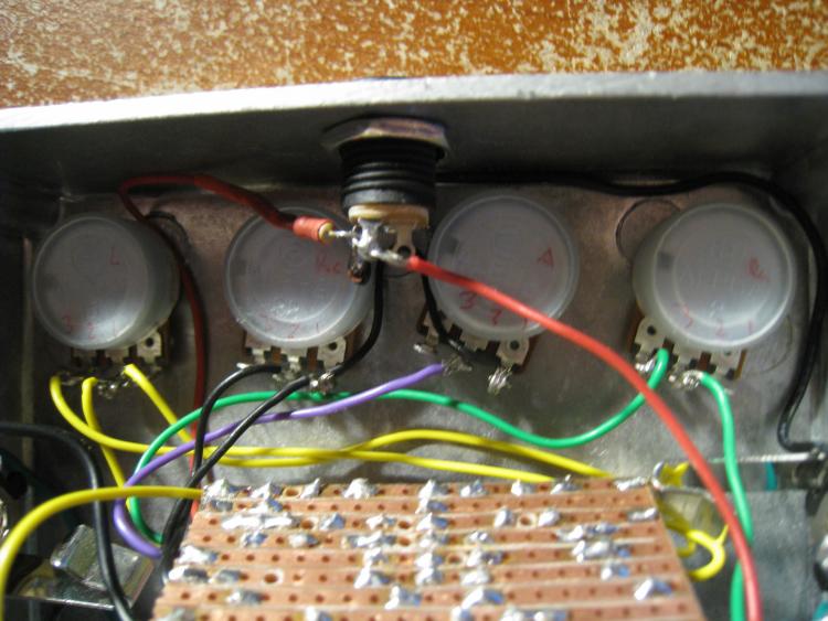
The output control works, but the ratio control seems to alter the output too, and I can't tell what the attack and release controls are doing since the only sound I get out of it is this farting sound. 
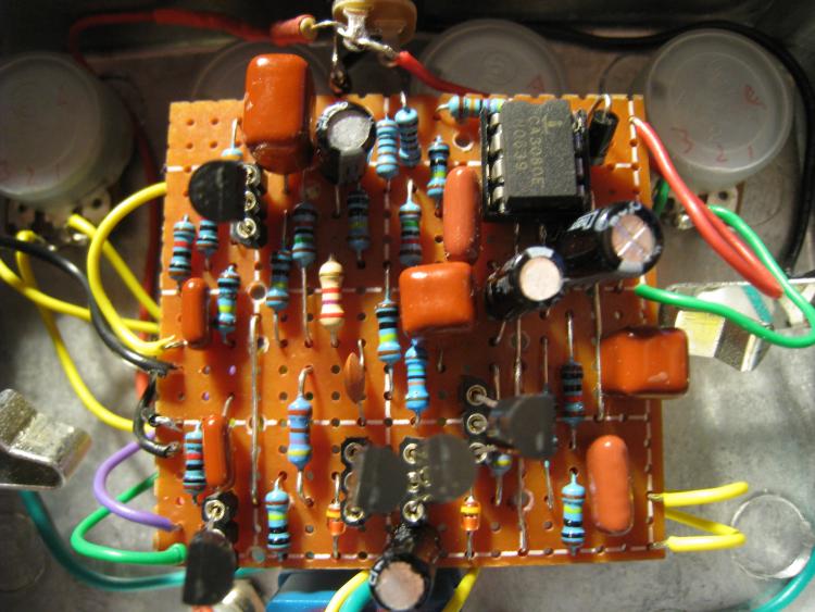
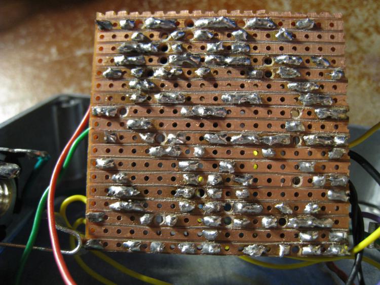
I checked for solder bridges, checked the wiring, cuts, and double links, and the diode position, but it all seems good. I need some direction to figure out whats going on. I was thinking it could be the IC, so I tried another and I still have the same issue. I've checked the transistors to see if they are all good, and they test fine. So, now I'm lost. Here are the Voltages I get. IC Pin 1: 0.000V Pin 8: 0.000V Pin 2: 4.60V Pin 7: 9.33V Pin 3: 4.60V Pin 6: 0.717V Pin 4: 0.000V Pin 5: 0.662V Q1 Q2 Q3 Q4 Q5 E 0.010V E 0.312V C 9.03V C 9.03V C 9.33V B 0.410V B 0.111V B 0.00V B 0.00V B 9.00V C 9.33V C 9.32V E 0.00V E 0.00V E 8.15V FYI: The readings on Q5 change when the attack and release pots are turned. |
|
Administrator
|
Here are some pictures of the board top and bottom respectively.
![]() FYI: some of the poly caps are physically larger or smaller, but are the correct values. They're just different versions of the Panasonic ECQ's. ![]() ![]() As usual, thanks for any help you can give so I can get this working and finally have a compressor. |
|
Can you double check those voltages on Q5? I'm certainly no pro, but nearly 9v on all three legs looks fishy.
Q: Why is a drummer like a scud missile?
A: Both are offensive and inaccurate. |
|
Administrator
|
Jopn, just double & triple checked and that's the correct voltage I get. I measured it by grounding the negative lead of my tester and using the positive lead at each leg. If I turn the ratio or attack knob the voltage at B changes for Q5, bot not a whole lot.
I'm no pro yet either, but I completely agree that something doesn't look right. I just cant figure it out. The sad part is I was serious. I'll have a bunch of builds that go perfectly, or I catch any problem that happens. Then, I'll do something completely different and just hit a wall, and can't figure it out. After building a bunch of fuzzes I have no issues then the first overdrive I built, the first booster, the first Ge transistor build, first 1590a build, now my first compressor I hit a wall and something happens that I can't figure out. I try to systematically check for the problem following steps, and going on things that I've dealt with before, but I can't figure it out. It's driving me crazy. |
|
I know how you feel, man, the last compressor I tried to build didn't work for no apparent reason as well, and now my latest fuzz doesn't work and I have no idea why. It sucks
I wish I could help you.
Through all the worry and pain we move on
|
|
Administrator
|
Thanks man. Right now I just put it aside to get some air and think. Hopefully someone who built it or has much more knowledge then me can help point me in the right direction. I would really hope that I don't have to take it all apart, and do a new board. I really don't want to loose more components.
|
|
Administrator
|
With a little help I was able to solve the problem. I accidentally added a 2.7k resistor in place of a 27k
. I have to be more careful, but at least I got it up and running, and it sounds fan-freaking-tastic. John K was right, this is a great compressor for guitar and with a small mod for low end retention sounds excellent for bass too.
|
| Free forum by Nabble | Edit this page |
