Two alternating preamp boards in the same enclosure (2 channel preamp)
|
Hi guys,
I've just built a model-t preamp and for distored sound it is great, but obviously I can't have a nice clean sound out of it. So I was thinking to build a second board just for clean sound and wanted to put the 2 boards in the same enclosure and be able to switch back and forth between the 2. Basically like switching on a regular amp that has a clean and a distorted channel. I'm having an hard time finding enough informtions about this idea. I'm not an expert in building pedals so I'd like to find a schematics which explains how to wire two boards together to avoid any issue. I just found some explanation on how to wire a 3pdt switch to A/B the two boards here https://www.diystompboxes.com/smfforum/index.php?topic=112539.0 But what about the power connection? I just solder 2 wires on the same lug of the power jack which go to the 2 boards? And what about for exemple of a bicolor led ? Or just 2 leds, to know on which channel I'm on? So do you have a link which explains all of this? Or can you help me to figure it out? I suppose that many people before me tried this thing, it's basically a 2 channel preamp pedal, nothing crazy right? :) Thank you very much |
Re: Two alternating preamp boards in the same enclosure (2 channel preamp)
|
This post was updated on .
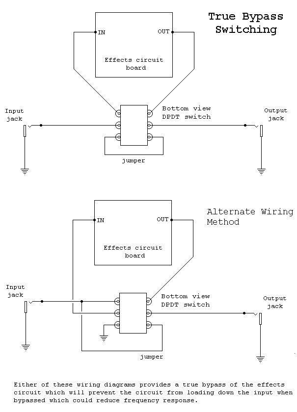
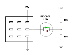
 The top diagram in the picture below is standard bypass wiring with a DPDT footswitch, so has no LED. You want to replicate this but replace the "jumper" bypass with your clean channel circuit. You could use a 3PDT footswitch and a bicolor LED to indicate status with the extra pole as in the next picture:  For power, you can just run two positive and two negative wires from a single DC jack and it will work fine. You could get fancy and use two separate low value resistors (e.g. 100 ohm) from the DC jack feeding two separate large electro caps to ground, but the circuit layouts you are using may well already have such power conditioning onboard. |
|
Ok thank you I think I'm halfway through understanding :)
What about ground? I normally follow this layout https://tagboardeffects.blogspot.com/2012/02/offboard-wiring.html How should I modify it? Connect the 2 boards ground to dc jack, as well as the input jack I suppose, then where the output ground goes? The bicolor picture, what is going on on the right side of the led? Does it represent the 2 boards? Is a 2 pins led or a 3 pins? I don't know what you're talking about on your last sentence so I suppose my layouts do the stuff :P I'm not really expert in electronics I just follow instructions :D |
|
Ok maybe I got the bicolor led layout,
The first 2 poles are as in the previous pictures, then the 3rd pole I guess is connected to a 2 pins led, so switching back and forth it changes the polarity allowing to change the color. Am I right? |
Re: Two alternating preamp boards in the same enclosure (2 channel preamp)
|
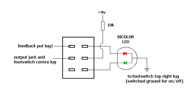
Sorry for the late reply. You are correct to say that the first two poles on your 3PDT footswitch will switch between the two inputs and outputs of your two circuits. The third pole is used for the LED, and the diagram I posted shows a type of bicolor LED that produces green light when current flows in one direction and red when current flows in the opposite direction. However, the bicolor LEDs I have personally have are called "common cathode", and they have a single ground connection and two separate positive connections, one for each colour. If this is the type you have, you need to take +9v through a suitable value current limiting resistor (e.g. 10k) to the central common pole on the end row of the 3PDT, and take the outer lugs on separate wires to the two different (+) anodes. The single cathode should be connected to ground: Ignore the left hand column/pole, the right hand pole on this diagram shows what I mean.
 |
|
Ok I see it, i think this way is better thank you On Tue, Aug 28, 2018, 08:45 nocentelli [via Guitar FX Layouts] <[hidden email]> wrote: Sorry for the late reply. You are correct to say that the first two poles on your 3PDT footswitch will switch between the two inputs and outputs of your two circuits. The third pole is used for the LED, and the diagram I posted shows a type of bicolor LED that produces green light when current flows in one direction and red when current flows in the opposite direction. However, the bicolor LEDs I have personally have are called "common cathode", and they have a single ground connection and two separate positive connections, one for each colour. If this is the type you have, you need to take +9v through a suitable value current limiting resistor (e.g. 10k) to the central common pole on the end row of the 3PDT, and take the outer lugs on separate wires to the two different (+) anodes. The single cathode should be connected to ground: Ignore the left hand column/pole, the right hand pole on this diagram shows what I mean. |
«
Return to Open Chat
|
1 view|%1 views
| Free forum by Nabble | Edit this page |


