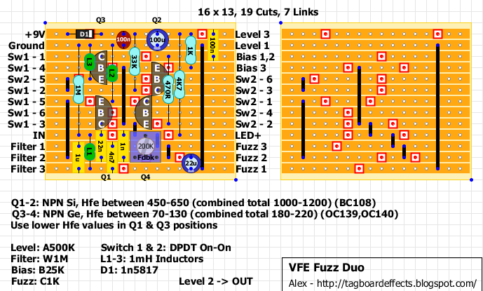
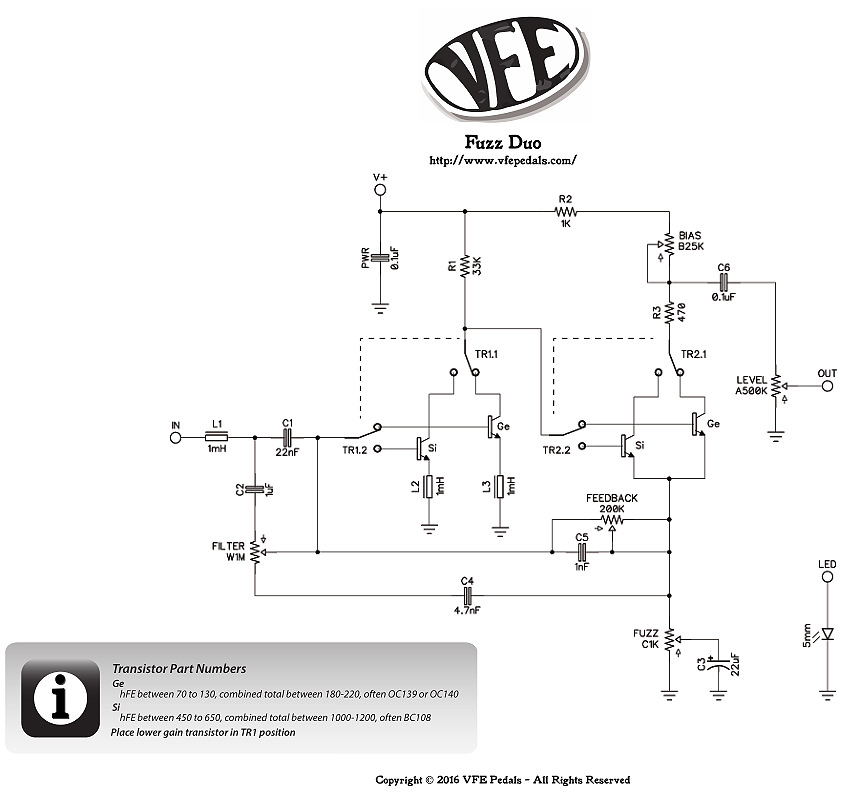
The input and filter sections look off.

Looking at the schem, the signal first
goes through the inductor and then splits off into the 22n and 1uf. The 1uf also
only goes to #1 of the filter pot, not #1 and #3.

I still used the layout with 2 little hacks. Having the inductor hanging off
board on the input, and moving the 1uf up so it connects from IN to filter #1
(at an angle). Filter #3 should only go to the 4n7.
I have a W1MC pot, but here's a photo of a production Fuzz Duo with a more
common A1M instead. I tested both and it works close enough:
https://i.imgur.com/jcUHJBO.jpg