Very close on giving up trying to build pedals...
Very close on giving up trying to build pedals...
|
I don't understand what I'm doing wrong. Two failed attempts at an Em Drive already. I'm sure the wiring from the 3PDT is perfectly fine, as I do get my guitar signal to come through when it's off and also when I turn it on the LED shines... But there lies my problem, when "turned on" only the LED lights up, no sound at all. If anyone could help me out with a drawn diagram of exactly which wires go to what pots from the board and what wires go from the pots to the 3PDT I'd highly appreciate it. But at this point I think anything is helpful :/.
|
|
Administrator
|
Post a pic of your build then we can see if anything obvious stands out
|
Re: Very close on giving up trying to build pedals...
|
My camera isn't great and won't let you really see detail. I can tell you exactly what I have wired though if you'd like. But I think I know where the problem is, I believe it's the ground leaving the Vero board. I sent the ground wire from the board to the volume pots "1st" lug. Was that wire supposed to go to the dc jacks grounding? If so, what do I do with the now empty lug on the volume pot?
|
|
I havn't built that one but plenty others , I would rund the ground from the board to vol pot lug 1 then to dc ground lug along with ground wires from input/output jacks
 Hope that helps and if you don't give up you could be addicted to building like the rest of us |
|
In reply to this post by isuckatguitar
My first ever project was building one of these: http://www.beavisaudio.com/bboard/
It's a simple interface to hook up unboxed boards, breadboards etc. Never looked back! Makes trying, tweaking and binning much quicker, takes a lot of the frustration out of the building and got me to build more and more quickly. You'll find not everything you'll build will be worth boxing up, so that will spare you all the wiring etc that add many variables in the equation (less things that can go wrong). Once you have put one together and made sure it's all wired right and ready to go (the continuity test on your DMM is your friend here, probe around and make sure everything is connected to what it should be connected to and nothing else - this is valid for your EM drive build too of course), you'll know exactly if your boards word and how they sound like. It's a fairly simple and straight forward build, and because of that a very great first one to gain confidence and practice with, not to mention something you'll never stop using through years of building pedals :) Good luck and don't let the first frustrating failed attempts stop you! |
|
I second Alex.s' suggestion, except I'd go with something far far less complicated until you get the hang of things.
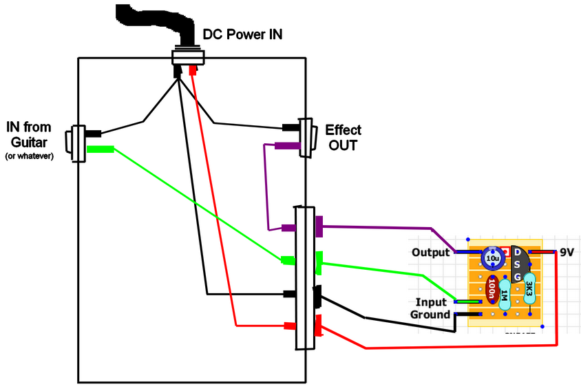
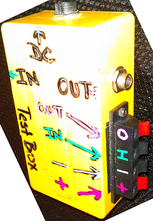
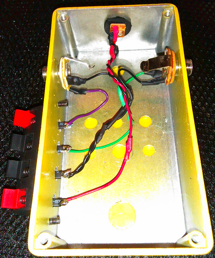
The concept is to test your pedal board with NO stomp switch, NO in/out plugs and NO dc jack. You should have wires coming from your board (twist the exposed end of your ground wires together because they are going to go the same place. I would recommend right now that you start picking a consistent color for these. I use BLACK=Ground, RED=DC+, GREEN=Signal In, Purple=Signal Out. It's not a necessity, but it saves me a LOT of headache when I know at a glance exactly which wires are doing what. Build yourself a quick and easy test box (you can get more complicated as you go along, but this is really all you need now). It really is super simple. I used a 1590B that I had mis-drilled and abused so it wasn't good for much else. Here's a crude diagram I spent about 5 minutes drawing:  That's just a simple buffer circuit, but they all work mostly the same. Sometimes your OUT will be coming from the VOLUME pot instead of right off the board. It still connects the same. This was there is no questions about your off-board wiring or faulty stomp switches, etc. This is pure and simple "does my board work" stuff. A lot of people test box their pots and other switches too. I can't be arsed to test box my pots, but it would not be hard to add a test spdt and dpdt switch to the test box. For those side connectors, I just used a cheap 4 connector speaker hookup terminal from Tayda, but there are numerous things you can use. Anything that you can stick a bare wire end into/onto/etc. will work.. screw terminals, alligator clips, etc. Here's mine: Outside  Inside  There are, of course, numerous ways of doing this and mine is not necessarily the best. Regardless of that, though, a test box will change your pedal building life. :) Honestly, if you don't have a spare 1590b enclosure to spare, you could build one of these in a Altoids can, an acrylic Seymour Duncan pickup box, a piece of wood (mount it all flat faced, would work fine), get creative :) Good luck and don't be afraid to ask questions. |
|
In reply to this post by isuckatguitar
Let me also encourage you to (1) not give up
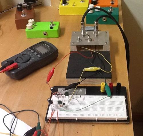
 and (2) make yourself a test rig. Mine is even simpler than Heath's, and allows me attach my circuit to +9V power (in my case from a battery), ground, input (from guitar through a 1/4" jack), and output (to amp through a 1/4" jack). I also have two switches, the first wired to provide true bypass (so I can quickly hear the bypassed signal versus the effected signal), and the other to switch on the power. Here it is in action with the EQD Speaker Cranker circuit on a breadboard: and (2) make yourself a test rig. Mine is even simpler than Heath's, and allows me attach my circuit to +9V power (in my case from a battery), ground, input (from guitar through a 1/4" jack), and output (to amp through a 1/4" jack). I also have two switches, the first wired to provide true bypass (so I can quickly hear the bypassed signal versus the effected signal), and the other to switch on the power. Here it is in action with the EQD Speaker Cranker circuit on a breadboard:
 Eventually, I'll add a +9V power jack so I can power it using a wall wart or battery. By the way, when I make a vero circuit, I include the wires but I don't solder the pots on just yet, but rather attach them using alligator clips. That way, if the circuit doesn't work out soundwise or otherwise, I don't have to desolder the pots to reclaim them. Also, when I box the effect, I mount the pots first then cut and solder the wires to length as I install the vero board. MUCH cleaner that way (for me). Have fun! 
|
|
Administrator
|
definitely build a test rig. mine is even simpler. i haven't made a box yet, but seriously have to, and just have the jacks attacked to wires and connected them to my breadboard, and simply use a 9V battery. seriously, don't give up isuckatguitar. i can tell you from my own experience, remember i've only been building effects for like 1 1/2 - 2 years, but the first 5 pedals i built didn't work at all, i spend days, weeks trying to figure it out. i ended up removing the stomp switch, which i wired using a different method then marks, and re-did them using the posted offboard wiring from mark. they all fired right up, so now i only use marks offboard wiring, and/or the pcb's stinger has for sell (look under the market place).
i still have 2 pedals that i built 2-3 times and still can't get them to work, i can't figure out at all what's wrong with them. i've had builds where the dumbest thing is the problem, like i had a build where i got bypass signal, i turned on the pedal and nothing, i took the jacks out of the enclosure, it worked. after hours of looking for things, i realized the leg of the jack was hitting the enclosure and grounding out, and once i moved it, it worked perfectly. i've put transistors in backwards, forgot to install them, and even installed ones that turned out to be bad, which prevented the pedal from working. can you imagine how embarrassing and frustrating it is to spend a few hours trying to figure out what's wrong with an effect, only to realize there's not IC or Transistor in its socket?  if you look at my posting history and at the threads about debugging help, you can see most of them turn out to be real stupid things. if you look at my posting history and at the threads about debugging help, you can see most of them turn out to be real stupid things.
don't get discouraged from building. it just takes time and patience. the more you build, and to be honest the more problems you encounter at the beginning the better you become. i've got a list of things to look for when i have a problem, especially for specific circuits, which helps me troubleshoot issues. but with your specific issue, check the transistor is in the correct orientation, check that's its good, check for cold solder joints, check that the arm of your jacks and board aren't grounding out, also check the continuity from the input to the output jacks tracing when the switch is engaged and disengaged. those's are the only things i can think of, without seeing the board. |
Re: Very close on giving up trying to build pedals...
|
In reply to this post by crw414
So I tried the ground from lug on on the volume to the DC ground and now the pedal won't light up the LED... And no sound still, but I am getting a pulse kind of sound and if I raise the volume on the pot, it gets louder, so the pot is definitely responding. I've also decided to definitely make a test rig. Thanks for the suggestion, not to figure out how to go about it. I must thank everyone on their input, it was all read, but I was away camping so I couldn't read or do anything about it until now. But yeah, thanks again. On Aug 29, 2014 5:51 AM, "crw414 [via Guitar FX Layouts]" <[hidden email]> wrote:
I havn't built that one but plenty others , I would rund the ground from the board to vol pot lug 1 then to dc ground lug along with ground wires from input/output jacks |
«
Return to Open Chat
|
1 view|%1 views
| Free forum by Nabble | Edit this page |


