Wampler Decibel+ Booster/Buffer Layout

classic Classic list List threaded Threaded
5 messages Options
Reply | Threaded
Open this post in threaded view
|

Wampler Decibel+ Booster/Buffer Layout

fx-fidden
This post was updated on .
Hello, this is the Wampler Decibel, a very simple IC Booster and Buffer.


I found some schematics of this pedal with some minor difference, and these are some spots, some details, where we can pay a bit of attentions:
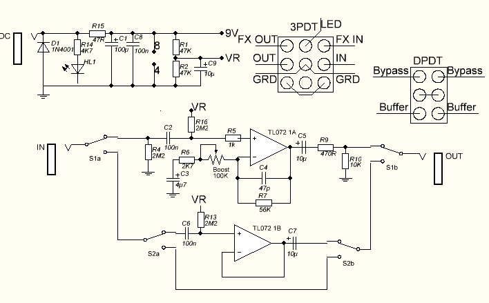
- The pair voltage bias resistors can be 47k or 100k resistors, I guess no difference.
- There's a version without the 2.2M to the voltage bias in the booster section. I'm not totally sure, but maybe we need it to make the circuit work.
- I saw a schematic without the pulldown resistor in input and output of the buffer. I prefer to include them, in case of pop when you engage the buffer, or maybe the pedals after it when the buffer is active. There's a 10k here, but once I used a 100k in a similar circuit with no issue.
- The output cap of the booster section can be 15uf or 10uF, but this circuit already has almost no low cut that probably will have no noticeable difference between those values.
- A schematic has a 500k pot for the boost control, but though it gets a smaller minimum booster setting at zero, a 100k rev log has a better tape.

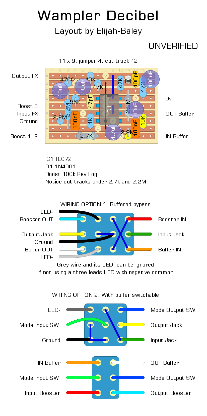
I included two options of wiring, drawing by myself. I think it's ok but both not verified.

The first one, with a 4PDT footswitch, has the buffer actived in bypass. When the pedal is engagaed you have only the booster actived.
There was a free lug, so I think to use a bi-color LED with three leads with a negative common. You'll have, for example, red light for the booster and green light for the buffer. If you want to use a simple on/off LED ignore the bottom side LED- wire.

The second option has a 3PDT footswitch and a DPDT (toggle or slide). The 3PDT is to engage or disengage the booster. With the DPDT you can choose between buffered bypass or true bypass.

Tell me if you see any mistake or somebody try to build it.
I build pedals
Reply | Threaded
Open this post in threaded view
|

Re: Wampler Decibel+ Booster/Buffer Layout

Axldeziak
Are you sure this is a Wampler pedal? The buffer is a JHS Little Black Buffer and the booster is a modified MXR micro-amp. I even found a few schematics posted in at least two DSB and FSB threads that says just that.
What schematics did you use to lay this out?
Reply | Threaded
Open this post in threaded view
|

Re: Wampler Decibel+ Booster/Buffer Layout

fx-fidden
This is the old version od the Wampler pedal:


This is the new version:


Well, the buffer is very simple and basic. I built the IC buffer, schematic by General Guitar Gadget, I guess is the same thing.
The booster section is very simple, too. A non-inverting input opamp boost, with a boost control enough similar to the MXR Micro Amp.

This is one of the schematic I have:

I build pedals
Reply | Threaded
Open this post in threaded view
|

Re: Wampler Decibel+ Booster/Buffer Layout

Axldeziak
The creator of that schematic says in this thread that it's his version of the MXR Micro Amp and JHS Black Buffer. It's not a Wampler Decibel.
Reply | Threaded
Open this post in threaded view
|

Re: Wampler Decibel+ Booster/Buffer Layout

fx-fidden
Yes, we can say that the booster is the Micro Amp. I didn't notice it.

Ok, this is not really the Wampler Decibel. Probably, I saved some schematics without reading the thread. I have another schematic, too, but very similar.

I found this image, it could be the old Wampler Decibel:


The opamp is the JRC4558. Ok.
Eleven resistors. Considering the Micro Amp schematic we have 10 resistors in the circuit, and one (the brown one) for the status LED.
One ceramic cap. It has to be the filter in the feedback loop of the opamp.
Three electrolytic caps and three polyester caps. Two electrolytic caps in the power filter, and we have to understand where placed the other one and the two polyester caps.
(I'd say the electrolytic in the output and the polyester in the "gain root". Maybe 1uF, I see one red cap is rather large).
The other two smaller polyester caps are the input cap of the booster and the buffer.

There's a transistor (?) and a diode. What is it? The switching system, I guess.
We have to look the 3PDT connection, too.

Anyway, I missed a cap. Let it go the poliester in the power supply, not so necessary, in buffer or booster a cap is missing.
I build pedals