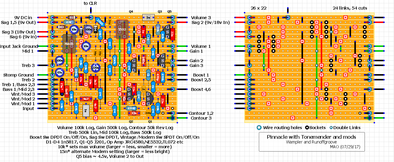
Wampler Pinnacle with Runoffgroove's Tonemender and a couple extra mods
|
This post was updated on .
CORRECTION 07/29/17 updated layout. The capacitor tied to Q5 drain should be 1u. Might want to socket this one. Lower value = less bass and visa versa. Also, I had better results with a NE5532 rather than the JRC4580 and TL072.
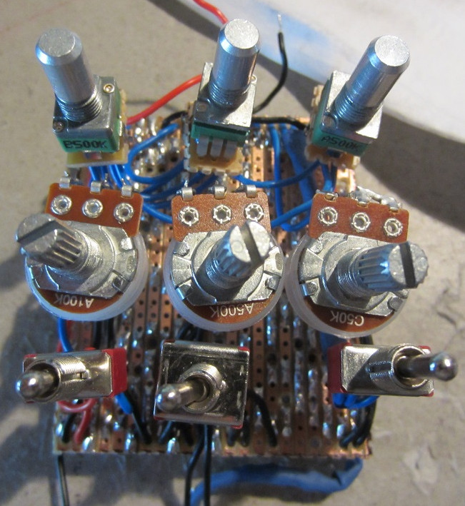
I had a request to add a 3 band tonestack and a sag control to the Pinnacle. I ended up mashing together the Pinnacle, runoffgroove Tonemender and Wampler Sovereign. I replaced the big muff style tone control with the Tonemender, kept the Contour and used the Sovereign's post-tone gain recovery output. I added a charge pump for the Sag control. I also added additional in-between boost and modern settings with on/off/on switches. I'm happy to report the layout is squeal free, I did eventually shield the input wire and vintage/modern switch wires, but had no noise prior so probably not necessary. The rest of the wiring was short enough not to need shielding. End result is the Pinnacle with a wide range of tone shaping. It's a little tricky to dial in as the tone controls and contour are very interactive, also affecting the volume. The layout was meant to be rotated CCW and fit into a 125B, with toggles at the top, this keeps the wiring short. But it works the other way around too if you want toggles at the bottom, just be sure to shield the input wire as that wire run will be a bit longer if board is rotated CW. I built a slightly different layout than the one posted, but the changes were minimal so I would say it is safe to call this one verified.  I used 9mm Tayda pots for the tone controls, standard 16mm for the others. 
1978 Gibson Les Paul Standard, Cherry Sunburst
|
|
I forgot to mention, I used a fixed 22k drain resistor for Q5, you'll want to select a J201 that biases around 4.5v when in the Sag mode (9v supply)
1978 Gibson Les Paul Standard, Cherry Sunburst
|
|
Bravo sir. Looks tremendous. Im gonna jump on this. With
 Are you indicating that links to say the ground or 9v/18v are both rows live etc? It looks blatent wnough but just want to double check. |
|
Thank you, and sorry, I had made notes for myself in the parenthesis for the power connections as I was figuring out how to wire the Sag switch. I just forgot to remove the notes.
All the red wires and connections carry supply voltages, green wires and connections are the grounds. The 18v out and 9v in lines (Sag 3 and Sag 6 connections) are only live when the Sag switch is in the 18v setting. This is to save battery power when using a 9v battery, no point in activating the charge pump until needed. I should mention, you will hear the charge pump wind down when flipping the Sag switch from 18v to 9v as the power supply is removed from the charge pump in the 9v mode. You can hear it wind down as the voltage discharges. Takes a few seconds, but I figure I wouldn't be flipping that switch mid song so the wind down noise wouldn't be an issue. However, if someone were planning to use a stomp switch for the Sag, maybe as a volume boost for leads of something, then you would want to have the charge pump powered all the time and would have to wire the Sag switch differently. As for all the ground connections, the "extra" ground connections labeled "Input Jack Ground" and "Stomp Ground" is where I grab the nearest ground from the board to connect the input jack ground and the ground for the stomp switch. This is to keep the offboard wiring short. I also use the Johnk inspired strain relief wiring holes indicated by the larger blue circles. I drill the holes just slightly larger than the wire. This keeps the solid wires I use from creating cold solder joints and/or breaking. For instance, the Sag 3 wire connects to the board at column 1, row 3 and then the wire itself routes through the board at column 1, row 4, comes out underneath the board and then connects to the switch. Not only does the wire routing holes help keep the offboard wiring neat and short, it also allows for removing the board from the enclosure without fear of any connections breaking off the board. Everything kind of stays together as a module, instead of flopping around. Plus I think it looks nicer too :0)
1978 Gibson Les Paul Standard, Cherry Sunburst
|
|
I believe I spotted an error on the layout, the cap tied to Q5's drain should be 1u, not 22nf.
Probably should socket this cap as it will most likely affect the amount of bass passing to the tone stack. I will update the layout asap.
1978 Gibson Les Paul Standard, Cherry Sunburst
|
|
Layout updated with proper cap value. (the 1uf cap between IC pin 5 and Q5 drain)
Also, I had better results with a NE5532 rather than a JRC4580 or a TL072.
1978 Gibson Les Paul Standard, Cherry Sunburst
|
|
Many thanks man, apologies not getting around to this, i just havent had the time at the moment, its in the pile of things to do. Clearing out old boxes and came across an n64, megadrives with the megacd attachemnet and various other consoles and just mega busy. Building asap.
|
|
Also, is it me or can i only see 53 cuts?
|
|
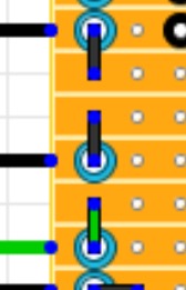
There's a cut top edge left for an optional wire going to an offboard CLR. It's under the blue routing hole indicator.
The cut is necessary.
1978 Gibson Les Paul Standard, Cherry Sunburst
|
|
Also, I think I ended up reversing the Boost 1 and Boost 4,6 connections.
1978 Gibson Les Paul Standard, Cherry Sunburst
|
«
Return to Booster, OD, Fuzz, Distortion
|
1 view|%1 views
| Free forum by Nabble | Edit this page |

