When pots go "out of range"
12


12
Re: When pots go "out of range" - NEW Question
|
that is what I said, that I tried Beavis it isn't working. I get a loud hum whenever I plug in DC. He wires his 3PdT differently. very frustrating.
|
Re: When pots go "out of range" - NEW Question
|
Time out - I need to rewire my foot switch, I see errors.
|
|
Oh, you want a battery and adapter? I misunderstood. It looks like you may have it sorted, but if not, here is what I use.
|
Re: When pots go "out of range" - NEW Question
|
Thank you! That Madbean is the one I eventually found before. I had forgotten about it. Dang, and I just tore this apart to start from scratch (on the footswitch and vero connections).
I love this site, but his "pedal build" guide is a little incomplete. He shows us all the connected jacks & pots, and then he says "and then I add the circuit board" and it just magically appears without him explaining how he managed to get all the connections made to the board when the Vero is upside down ;-) I am just kidding - it is a great guide, but not all of us are as organized or want to skip having battery options. In fact, I tried his wiring method and it doesn't work for me - he doesn't go into detail about grounding the board and jacks together. Neither does beavis really. they show it but it doesn't always work. I guess it is one of those things that if you know how to do it, it is simple, but if you are still learning one little thing wrong makes a big difference - at least for me. I don;t usually have to struggle for hours to figure out a simple thing like this, but I still get a loud buzz every time I plug in the 9v. When I had just the circuit I killed it by jumping from the DC connector to a ground lug on a pot, but I can;t seem to find the magic spot in this circuit. |
Re: When pots go "out of range" - NEW Question
|
In reply to this post by induction
I just wanted to say "thank you " again for all who helped. I got the pedal working and boxed today. madbean was the ticket I needed to sort out the grounding problems I was having.
Being a noob - geeze: 1) I burnt out a 4559 (I believe) by installing it backwards. I was taking it out every time I soldered the board and that last time I reinserted it I did it backwards. Not ily did the circuit not work, but the IC felt really hot to the touch when I took it out. Putting in a new one was the first step to getting this thing working. Next - I had never populated a box first and then added the circuit board after, so my leads were too short (in some cases, and in other cases too long) to wire the board component side up. Somehow, without even realizing what I was doing, I wired it in there component side down.  But with some double sided tape it works fine. My only issue is that I really should have bread boarded the design and found the right values for resistors to go with the pots. Both of my pots act like volume controls, but in different ways - so I will go back and fix it someday. but it sounds good now anyway and is usable. It is boxed up, has a working LED, and sounds great. |
|
Administrator
|
motter, always glad to help, and really glad you got it working. if it makes you feel better, i built a 78 dual op amp big muff 2 days ago went to install one of the IC's and one lead kept bending out of place and broke off. got put a new one in in fired her up and i bearly going signal, i started to go over it all and realized i installed the wrong IC both times, so i put in the right one and still get a similar issue, but i got fuzz. i start going over the whole board, re-score between the tracks, everything, still cant get it working, all of a sudden i realize that one of the electrolytic caps is backwards, i desolder it, resolder it correctly and it fires right up.
it happens to us all, noob or not. it comes with the job. i feel like the more you build the more i expect stupid stuff to come up to prevent my builds from working. keep up the good work man. 
|
Re: When pots go "out of range" - NEW Question
|
Thank you for the encouragement.
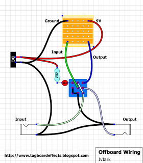
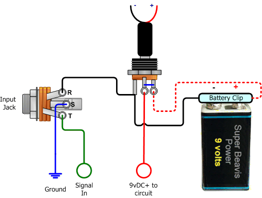
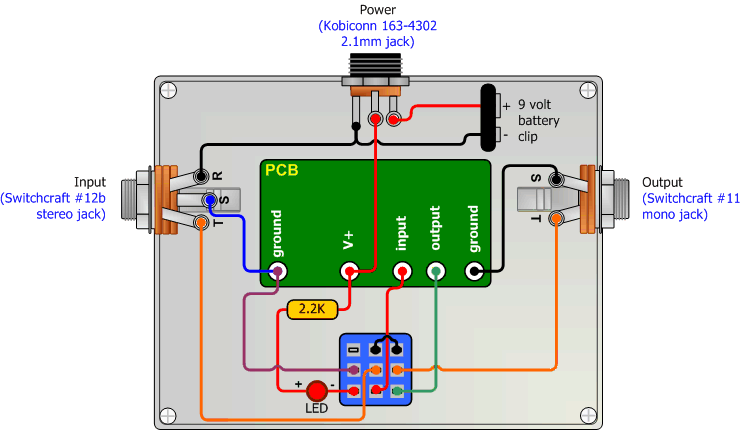
I just want to point out once again that grounding is always the issue for me. I guess the rule is that it should be one big line - constant ground, but you do need to to start and end someplace. MadBean shows you connecting ground to the board, footswitch, DC adapter, LED and both jacks. Not saying this is wrong, but it doesn;t show the battery and in my circuit it gave me hum:  Then with Beavis, this image shows how to connect a battery, but not the board or footswitch:  This one is better, but I had the footswitch wired a different way, so I also got hum with this.  This MadBean: http://www.madbeanpedals.com/tutorials/downloads/StandardWiring_MBP.pdf right here is the only full graphic that has worked for me for getting all my ground connections right. This will be my first reference from now on - it could have saved me a full 24-hour day between yesterday and previous builds. |
|
Administrator
|
the beavis one does show the battery connected to the switch. remember the battery is only switched on if there is a plug inside the stereo jack, and no plug in the DC jack. otherwise it is disconnected from the circuit so that it does not drain.
|
Re: When pots go "out of range" - NEW Question
|
Yeah, I edited my post a few times as I looked ta the diagrams.
This site (what do they call this site anyway) shows the footswitch wired tha same as MadBean, whereas beavis uses a different footswitch layout. Furthering confusion, I am pretty sure this site's picture of the layout where he shows an actual pedal before he drops the circuit in shows the footswitch wired a different way. Now - I realize it doesn't matter exactly how the footswitch is wired as long as it makes the right connections, but for me certain diagrams are just easier to see than other ones. I suspect we are all somewhat different in that sense. |
|
Administrator
|
exactly. there's more than one way to wire the stomp switch, due to the way it makes contact when the switch is pushed. me personally i stick the one one you posted from mark, which appears to be the same as madbeans. as long as you follow the correct steps for that layout you're good to go, and stick with the same method so that you're consistent and don't get confused. i still bring up the wiring when i do the switch, because i worry i'm going to do something stupid.
side note, i'm not sure about what this forum is called, but the main site is tagboardeffects. and in case no one said it welcome. 
|
Re: When pots go "out of range" - NEW Question
|
Thank you - you guys have been most helpful - which means a lot. I run a forum for a living myself ( about cruise travel).
This pedal building is addictive - and I try to keep going to completion because I know the more I do it the more rote it will become. BTW: I can't find them now - there is a small pedal building thread on Ampgarage.com. Someone there pointed out a PCB that sits on top of the footswitch in a certain size enclosure and it gives you holes for that plus two standard 1/4 jacks (the barrel kind) and the 2.1mm DC jack; plus connections to the circuit in/out; 9v and ground. All you have to do is fit the PCB onto the switch. Really makes sense, since that is where I usually mess up. however, now that I have the right road map I think it will be a lot easier. I made my first pedal just a couple months ago - KlonE (from a PCB and kit with all the parts for $99) - came out fine although I did make a few mistakes. Then I went to Beavis and started breadboarding which is very cool, but there are not enough examples out there. I would love to breadboard the circuits here but it's pretty hard to translate them (I have done a few). Since then I have built the Brian May booster (very cool for such a small circuit), the Mockman, and some kind of fuzz. The funny thing is that that I don't even use drive pedals, I use tube amps with gain channels, I like tube distortion. But so many of the pedals sound good enough that I just might change to pedals instead. I just found this forum, too: http://buildyourownclone.com/ - very active. But I like what they are doing here (there is some negativity about vero board out there) - a lot of people prefer making PCBs which actually seems like not a bad idea. |
|
Administrator
|
1 - there are pcb's that you can put over the stompswitch that can make the offboard wiring much easier. one of the guys in the community, stinger, is selling them really reasonably priced. i just bought 50 to give them a try and will be using them on my next build tomorrow. they look fantastic, are priced well, plus if you get them from him you're helping someone in the community. here's the tread where he's selling them, if you are looking for something like those i suggest getting them from him.
2 - breadboarding can be difficult to learn, it took me awhile, and induction, one of the guys here, really helped me better understand it. there are tons of tutorials out there. and if you want i can email you some. one thing to remember is that whatever you do to breadboard one circuit, you will use the same skills/methods/tools to breadboard any other circuit. take a look at these two links from smallbear, this one is just about using a breadboard, and this one which has directions for a bunch of different projects that they sell that are based on common circuits. definitely a good read and starting point. 3 - i've build pcb's both ones you can buy, and those that i've etched myself. there are positives and negatives to them. if you etch your own you have to work with acid that can be dangerous, plus it takes a lot of time to do since you have to transfer the circuit design to the copper board, etch it in acid, clean it, remove the left over transfer, drill the holes for the components.....i think you get what i mean about time, lol. the positives is that you can fit a large circuit onto a smaller space that you can on vero sometimes. after doing both, and some may disagree with me, but i really prefer working with vero, despite having to make sure each cut and link is correct and there's no bridges and such, in the end its all handmade by me, i'm not just propagating a pcb, and in some cases it's nearly all point to point wiring since every component is so close together. |
Re: When pots go "out of range" - NEW Question
|
Thanks Rocketman - the first link to the guy selling the footswtch PCBs did not work. I do want to buy some.
I see your point about Vero. I have not had much trouble with it, really, other than when I try to mount it in a board with the grounding issues. It is easy to do. I can usually have a board cut and populated in a couple hours. Making the cuts seemed a hassle at first, then I saw a post where a guy said he just takes a drill bit and does it by hand - a few twists and the copper is gone. But first you drill the other side with just slightly larger holes so when you flip it you are sure you have the right spots, and the larger holes help to center the larger bit. |
|
Administrator
|
yea i drill mine out then use a very large drill bit to remove the copper connections, and this way from the top when i populate the board i use the cuts as a reference point, it seems to help prevent me from putting components in the wrong place.
not sure why the link didn't work, just go to the "Friends Market" and click on the thread labeled 3PDT true bypass wiring pcb's by stinger, link. |
|
In reply to this post by motterpaul
Hi Motterpaul,
I know I am late to the thread, and this may cause confusion, but I used this wiring tutorial by Gaussmarkov, which is really clear and easy to follow. I use it on all my builds. To add a battery snap (which I normally do), red battery wire goes to outer lug on your power socket, and black battery wire goes to "sleeve" connection on your stereo input jack. http://gaussmarkov.net/wordpress/thoughts/wiring-up-a-1590b/ |
Re: When pots go "out of range" - NEW Question
|
Beaker ....
Nice visuals on that wiring guide. Thank you. I see it also uses the same layout for the foot switch as this site uses (with the U wire between 3 and 7) - Do you use non-stranded wire and bend it to shape do go down the sides and along the edges of the switch? |
|
Yes I do. I also use this for the input/output/ground. makes things nice and neat.
http://www.doctortweek.co.uk/shop/article_67/Hook-Up-Cable---Evolution-XTC-Screened-1m.html?sessid=LcsLApWHq0OllKfDSOjBhkCJ3gtNMCr8elmiBBxtHQJIRhbWVPpqaQeNe2kzZdLx&shop_param=cid%3D37%26aid%3D67%26 |
«
Return to Open Chat
|
1 view|%1 views
| Free forum by Nabble | Edit this page |

