Wiring filtering diode+cap at dc power shocket

classic Classic list List threaded Threaded
15 messages Options
Reply | Threaded
Open this post in threaded view
|

Wiring filtering diode+cap at dc power shocket

traktop
This post was updated on .
I´m ready to wire my ´73 Rams Head Big Muff Build.
http://tagboardeffects.blogspot.com.es/2012/06/ehx-73-rams-head-big-muff.html
Following JaviCap advice, I want to wire the diode and filtering cap between positive and ground at the dc power-shocket, so it just will operate when external power provided but not when using the battery, (he even told me not to use a power shocket at all, but I´d like to have it there just in case...).
I thought I just had a clear wiring picture in my mind, but when tried to translate it down to paper, I just don´t get it...
My goal is being able to power the circuit with the battery straight to the circuit with no filtering at all, but when a power suply is connected, the power gets filtered by the diode and the 100uf cap soldered to the power shocket pins, (1-2/3 pins).
As I see it, a plug should be always connected to the shocket in order to short and isolate both positive pins. Otherwise, the battery power would be always getting drown by the power filtering at the power shocket.
Any idea?
Cheers, Gilberto.
Reply | Threaded
Open this post in threaded view
|

Re: Wiring filtering diode+cap at dc power shocket

Ciaran Haslett
I think you're right.  I can see no way of wiring this up without the battery supply being filtered also.  You could add a switch to add/remove any filtering but that seems pointless to me.

If you permanently plug in a DC jack plug, you break the battery circuit so that wouldn't work either.  

I'm not sure how Javi would have done this.
Reply | Threaded
Open this post in threaded view
|

Re: Wiring filtering diode+cap at dc power shocket

induction
Power filtering is useful for batteries as well. It helps avoid oscillation, especially in high gain circuits. Ripple on the supply rail comes from current draw as well as regulation. I don't see I down side to using the filter cap with a battery. As for the diode, use a schottky and the voltage drop will be very small.
Reply | Threaded
Open this post in threaded view
|

Re: Wiring filtering diode+cap at dc power shocket

traktop
From the thread:

-"I've built it without diode and without filtering cap. While with battery works awesome, with power supply is a unbearable noisy box, so I had to add the filtering cap, but did it on the DC jack, not on the board, so, it just operates when pluged to the power supply.
For what I could read about, this effect did not have protection diode, nor filtering cap.... nor DC Jack. So, I have to tell that while its sound is just unbelievable when used with battery, with power supply, is still a bit noisy, and the filtering cap CHANGES / affects the tone, so I believe, this is a clear candidate to be always powered with battery and forget about the PS."

He also told me that another option would be trying lowering the filtering cap until I find a good compromise between tone/noise.
Maybe I better leave it just with battery and forget about PS as he said.
Cheers, Gilberto.
Reply | Threaded
Open this post in threaded view
|

Re: Wiring filtering diode+cap at dc power shocket

induction
traktop wrote
From the thread:

-"... while its sound is just unbelievable when used with battery, with power supply, is still a bit noisy, and the filtering cap CHANGES / affects the tone...
Have you verified this change in tone yourself? With all respect to Javi, I'm a bit suspicious. It seems far more likely that he had a build error.

I also don't see how it's possible to wire the filter cap onto the socket in a way that it won't be connected while using a battery. So again, I suspect that Javi was incorrect about exactly what he implemented.

In any case, if you want it to run quietly without batteries and don't want to use a filter cap (or even if you do), just use a regulated adapter. That should be as quiet as a battery.
Reply | Threaded
Open this post in threaded view
|

Re: Wiring filtering diode+cap at dc power shocket

traktop
My power brick is a voodoo lab power pedal, so that should be ok.
I didn´t verify it yet, but I will try several things and post my results as soon as possible.
Cheers, Gilberto.
Reply | Threaded
Open this post in threaded view
|

Re: Wiring filtering diode+cap at dc power shocket

Travis
Administrator
In reply to this post by induction
I do this often when trying circuits on my breadboard. With the fuzz face I always leave it without the ripple cap. It seems to dampen the tone slightly with the fuzz face while not really helping with noise much at all. The diode in series with the supply doesn't seem to make any difference assuming it's only creating a small voltage drop. So I usually recommend the diode, because it offers good protection without affecting the sound.

Sometimes the ripple cap will cause an oscillating fuzz to stop oscillating, or cause some other difference to the sound. The ripple cap is almost always a good thing, except occasionally when dealing with some fuzzes
Reply | Threaded
Open this post in threaded view
|

Re: Wiring filtering diode+cap at dc power shocket

induction
Travis wrote
With the fuzz face I always leave it without the ripple cap. It seems to dampen the tone slightly with the fuzz face while not really helping with noise much at all.
In a fuzz face, I can see it, but the muff is a very different circuit, and I wouldn't expect similar behavior from it. But Gilberto should trust his ears over my skepticism.

And I agree, filter caps aren't much help in fuzz faces. A battery or a regulated adapter is the only way I've found to keep them quiet. Purists will say that shitty carbon zinc batteries from the dollar store are the only acceptable option, tone-wise. Decent alkaline batteries are no good, and only marginally better than lithium or adapters. This is one case where I can actually hear the difference, but mostly for Ge transistors. With silicon, it's not nearly as noticeable. But again, I wouldn't expect this result to generalize to muff circuits.
Reply | Threaded
Open this post in threaded view
|

Re: Wiring filtering diode+cap at dc power shocket

Travis
Administrator
induction wrote
Travis wrote
With the fuzz face I always leave it without the ripple cap. It seems to dampen the tone slightly with the fuzz face while not really helping with noise much at all.
In a fuzz face, I can see it, but the muff is a very different circuit, and I wouldn't expect similar behavior from it. But Gilberto should trust his ears over my skepticism.

And I agree, filter caps aren't much help in fuzz faces. A battery or a regulated adapter is the only way I've found to keep them quiet. Purists will say that shitty carbon zinc batteries from the dollar store are the only acceptable option, tone-wise. Decent alkaline batteries are no good, and only marginally better than lithium or adapters. This is one case where I can actually hear the difference, but mostly for Ge transistors. With silicon, it's not nearly as noticeable. But again, I wouldn't expect this result to generalize to muff circuits.
Right, I wasn't really trying to generalize here, only pointing out that the ripple cap can occasionally cause an appreciable difference in sound.

Like you, I'm skeptical how much difference it will make in a big muff. I also encourage Gilberto to test the difference with his own ears.

Thanks for the good advice as always, induction
Reply | Threaded
Open this post in threaded view
|

Re: Wiring filtering diode+cap at dc power shocket

traktop
This post was updated on .
In reply to this post by induction
Finally tried it today.
I made some changes following kitrae website to make the first revision of the"violet ram´s head".
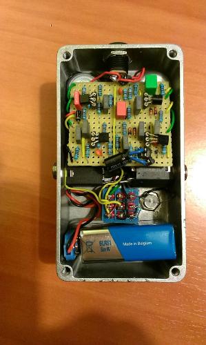
I left the diode on the board and shocketed the 100uf filter cap.
External powering definitely introduced much more noise than the battery, (with and without the cap). The battery alone made it sound open and cleaner. When introduced the 100uf cap, it seemed to loose just a little of something, but nothing remarkable and clompletely usable. I wouldn´t use it without the cap with external powering though...
Anyway, I dropped four bc550´s without measuring gains and stuff and compared to a NY reissue that I had around this thing sounds just gorgeous and classy.
Other options are 2n2222a and mps18 that I will probably try due to curiosity, but this seems to be the perfect combination of buzz, clarity and sustain that I always expected from a big muff, (nothing spectacular, but irreplaceable in my opinion).
Thank you guys
Reply | Threaded
Open this post in threaded view
|

Re: Wiring filtering diode+cap at dc power shocket

Travis
Administrator
Nice job Gilberto! BC550C are perfect for muffs. It never hurts to try other stuff, but the BC550C will pretty much always give great results in muffs
Reply | Threaded
Open this post in threaded view
|

Re: Wiring filtering diode+cap at dc power shocket

traktop
This post was updated on .
It sounds great indeed, thanks!
Other muff that I tried was a Biyang fuzz star, (big muff clone), that didn´t sound so bad after mods.
That one had that kind of sustain that allows you playing notes effortless just moving your finger up and down around the neck forever without picking any single note.
There it goes my interest on higher gain transistors like mpsa 18´s
Reply | Threaded
Open this post in threaded view
|

Re: Wiring filtering diode+cap at dc power shocket

rocket88
Administrator
speaking from experience the higher the hfe the more treble you'll get in the overall effect, while the lower the hfe the more bass you'll get. i personally wouldn't go below 300hfe as it just doesn't sound all that good IMHO. plus it can screw up the bias.
Reply | Threaded
Open this post in threaded view
|

Re: Wiring filtering diode+cap at dc power shocket

Travis
Administrator
rocket88 wrote
speaking from experience the higher the hfe the more treble you'll get in the overall effect, while the lower the hfe the more bass you'll get. i personally wouldn't go below 300hfe as it just doesn't sound all that good IMHO. plus it can screw up the bias.
What's interesting is that the readings I've seen from original triangle muffs are relatively low hfe (consistent with the 2N5133 we see for sale currently).

Obviously later versions of the Muff used a variety of transistors, most with much higher hfe
Reply | Threaded
Open this post in threaded view
|

Re: Wiring filtering diode+cap at dc power shocket

traktop
This post was updated on .
Finally I won´t change anything.
I measured the rest of my little bc5088 stock and all measured between 460-500, so mine should be on that range.
I was curious about other transistors, but it´s been two days playing with it and I just love it!
It sounds creamy and clear. It can cut but never harsh at all.


Big thanks to everyone!