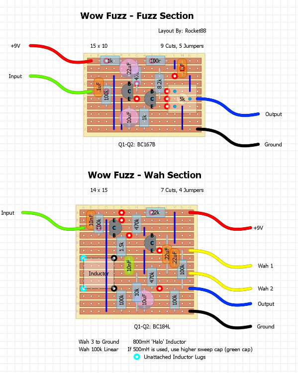
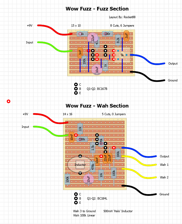
i've been trying to figure out a good, neat, working layout for this effect and think i've finally figured it out with the proper transistor pinout, rather than the "CBE" seen in the schematic. i would really appreciate it if someone with another good set of eyes could just check both of them out for me to make sure I didn't miss something stupid compared to the schematic.
If everything looks right, I think I found a way for me to check my layouts very accurately to help cut down on questions like this and I can contribute more.
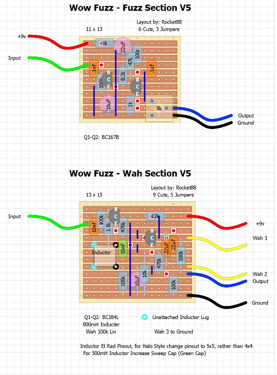
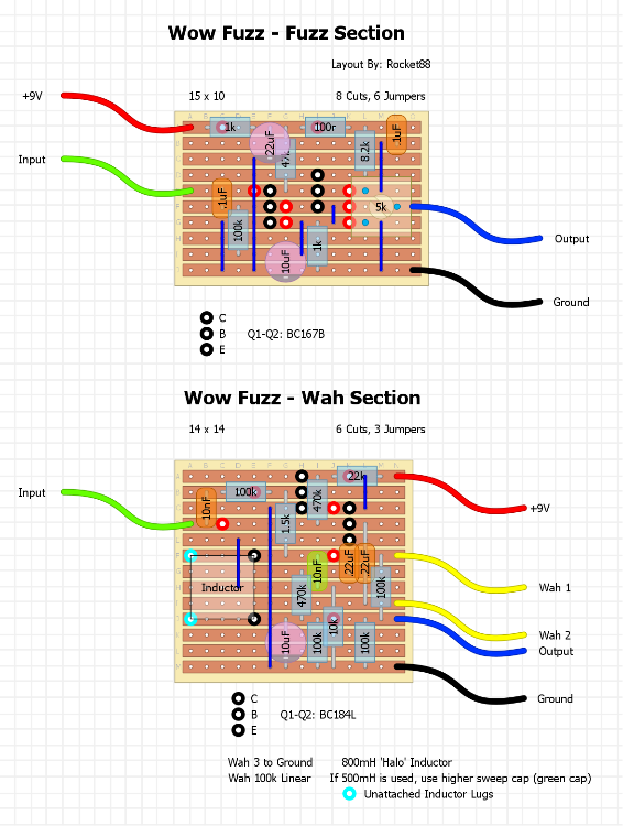
I changed the pinout for the inductor, since I had one custom El Rad style made for me, rather than the halo I had. Also, the trimmer is 47k in the reissue, which I may use instead of the 5k.
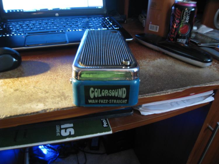
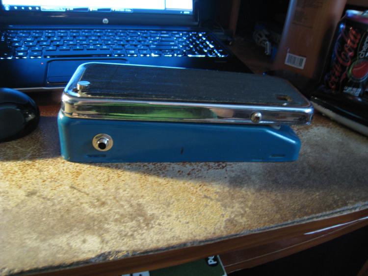
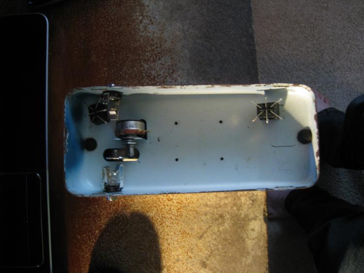
Gratuitous shots of the colorsound enclosure that will receive the completed effect.


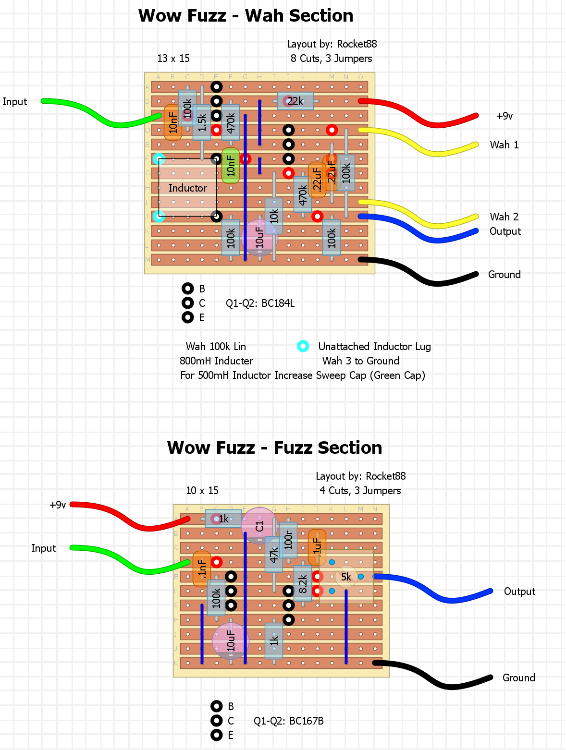
 i made the changes you and tried to shrink the layout a little bit. I did notice that I built both layouts looking only at the schematic, but did not pay attention to the pin out of both transistors, as they are both BCE, rather then CBE. What it the easiest way to rearrange both layouts to mimic the pinout, so I don't have to twist the transistor legs?
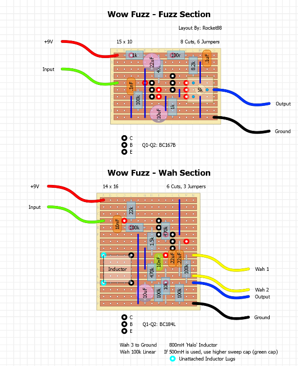
 . Once I went to make the changes, and keep all the resistors flat it became a complete redo. I have an idea to help me visualize how the layout should be arranged. I'm printing out the schematic and going to label the pinout and try to "rewrite" the schematic with the transistor shown as it is in reality. (not sure if that sounds the way I'm thinking it,
  . basically try to make the schematic match the mechanical appearance of the transitor).