ZVex SHO mosfet voltages
|
Hi everyone. I've just built an SHO and though it sounds more or less nice, I think it isn't sounding as good as it should be. There is no noise nor hiss in the build, and the pot is working properly. At low pot settings it sounds better, but when the pot passes two o'clock you can notice the harshy and cheap distortion. I've tried with several kind of transistors and they gave me very similar results, here come the measurements I've done with a 9v battery: BS170P By DiodesZetex D G S min 5.04 0.49 0.72 max 3.66 0.48 0 BS170 By Farchild D G S min 4.94 0.50 0.58 max 3.93 0.50 0 VN10KM by Siliconix D G S min 4.75 0.51 1.15 max 2.52 0.49 0 I' m not an expert but I find intriguing that no matter the transistor I put on, the voltage at the gate it's always the same (around 0.50v). Do you think that's ok? If someone with a good sounding SHO could do this measurements in order to compare with mine, I would be very grateful. |
|
This post was updated on .
After a while I realized that I was getting different results when the effect was in bypass than when it was ON. I've removed the LED from the circuit and now it sounds better. Take a look at the test I've done:
No led, no resistor D G S min 6.78 0.73 1.55 max 3.88 0.72 0 Led + 4.3k resistor D G S min 5.30 0.53 0.90 max 3.78 0.54 0 Led, no resistor D G S min 1.88 0.15 0 max 1.88 0.15 0 I don't know if these results are ok or not. To be honest, I wasn't expecting the led to change that way the transistor behavoiur. I would like to have the led but...It's working better without it. |
|
That is weird indeed.. It shouldn't have any effect A.F.A.I.K...
Is it possible to post pictures? I know it's a PCB, but maybe we can spot a bridge somewhere or something? |
|
Hi Marbles. I took some pictures:
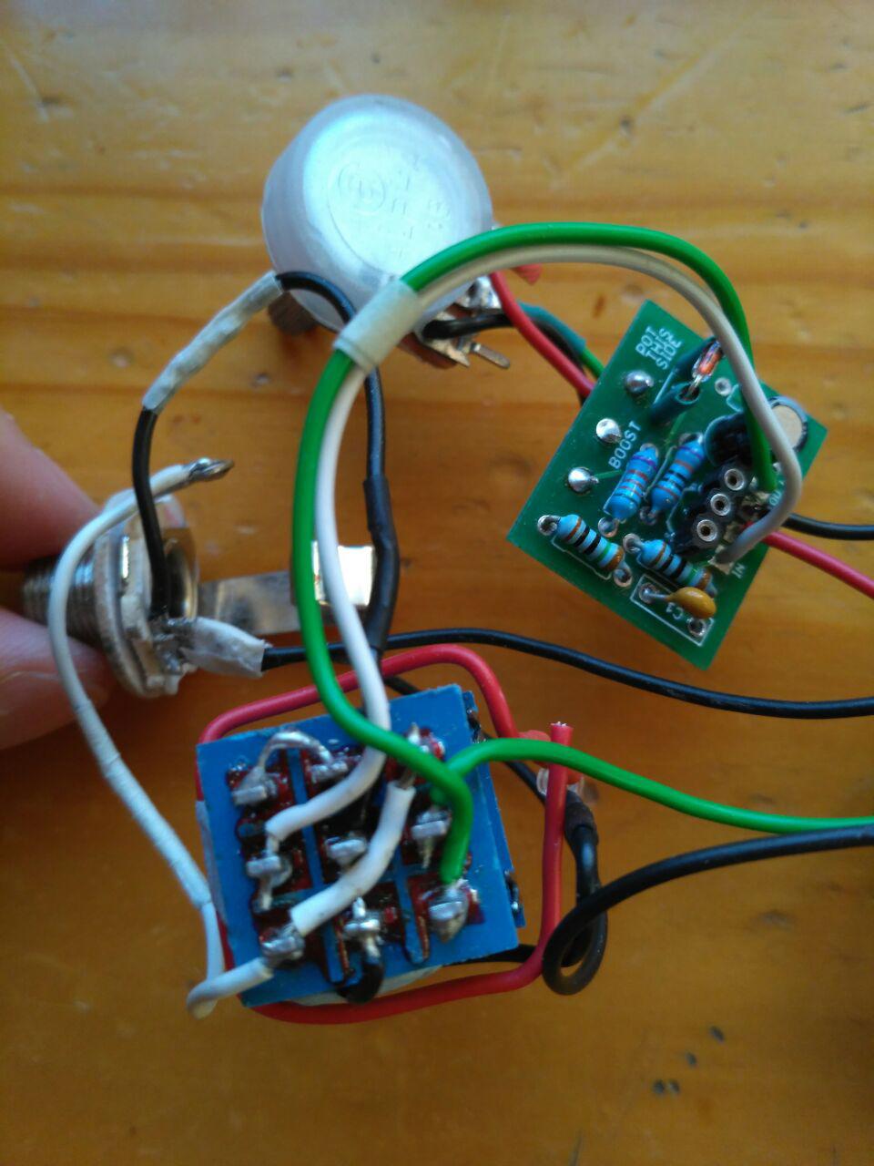
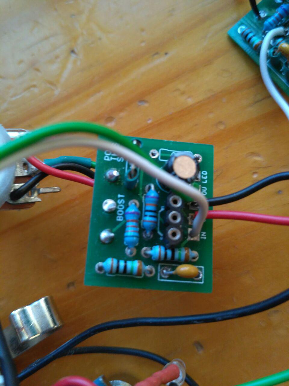
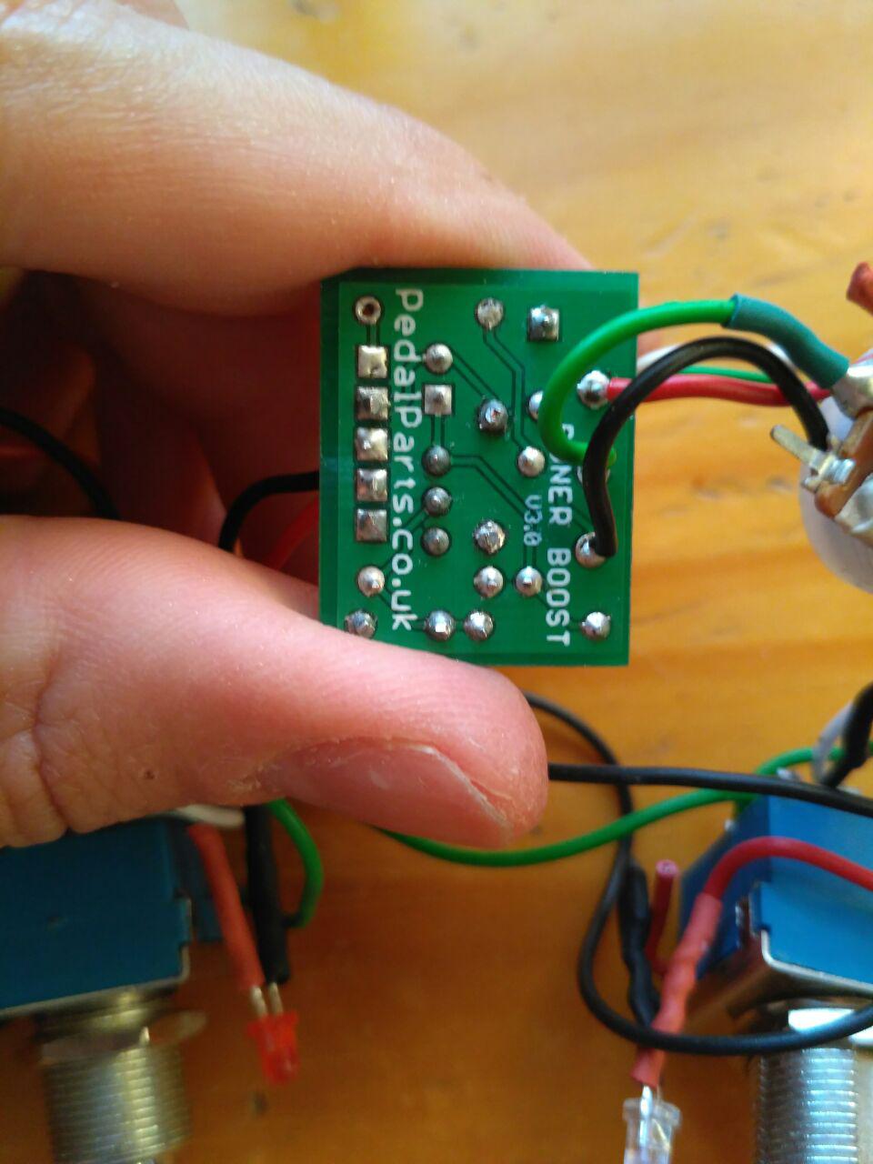
1) Input jack, C5k pot and PCB  2) Front PCB  3) Back PCB  4) Switch wiring  I've removed a couple things: the led resistor from the pcb and the hot wire that comes from the pcb to the led's anode. I've tried connecting the led right into the 9V from the battery but same results. The pedal is working well, but without led :S The problem comes when you connect the led to the circuit and then the voltages drop. |
|
Administrator
|
How do you have the LED wired in? Are you using a dead battery to test the circuit?
|
|
Administrator
|
First of I would contact the guys that made the PCB because there's a lot that doesn't make sense. The LED should not be sucking power away from the pedal circuit to the point that it changes the sound, cause that tells me that the LED is somehow in part of the signal flow which it shouldn't be.
Secondly I only see 1 jack, assuming the input jack, which appears to be a mono jack, what is the output jack, mono or stereo? If you're using a battery are you using a DC jack too and what kind? Typically if you're running a battery you want the battery off when nothing is plugged into it, so you would use a stereo jack that switches the battery when a cable is plugged in and DC jack with 3 lugs (2 power, 1 ground). Also, I would take a look as the soldering on the jack, it doesn't look good to me. |
|
In reply to this post by nonost
Is it possible you have damaged this wire?
 Maybe the crossing wire is a bit stripped, and the LED wire that sticks out is making contact? You could lift the crossing wire up and check if that changes anything? |
|
In reply to this post by Travis
Hi Travis. If that's the switch: 1 2 3 4 5 6 7 8 9 the anode is a black wire that goes to pin 8. The cathode goes straight to the pcb, but now I have removed it (it's the red wire that you can see around the switch). In the pcb is where you install the resistor for the led as well. The battery it's pretty much new. I've only used it for testing porpuses. |
|
In reply to this post by Marbles
Good eye Marbles but I'm afraid that's not the problem :( I've tested and everything is fine there. Actually, I've tested among all the pins and all of them are ok.
Are you getting differents voltages when the led is ON as well? |
|
Administrator
|
This post was updated on .
In reply to this post by nonost
In that case, you installed the LED backwards
|
|
Sorry, I switched between both terms. It is the cathode(black) the one that goes to the switch and the anode(red) to the board. For a moment I thought I'd put the color wires wrong, but they are ok. |
|
This post was updated on .
In reply to this post by rocket88
Hi rocket88. You're totally right about the soldering in the input jack. I know it looks awful, but I've done and undone this soldering a couple times and I always get that ugly result. I've tested a few times and the continuity is good. Anyway I'll try one last time.
About the DC jack and stuff...Yeah, I'm aware of how it works. I'm using a battery till I put the pedal in the enclosure, but I'm not going to add a battery clip so my two jacks are mono. Lastly, maybe it is doing what it should do...The thing is, are you getting drops in the voltages when the pedal is engaged? Many thanks to you all, this web site it's absolutely great :) |
|
Administrator
|
No the bypass switch should not affect the voltages
If the battery that you're using is fine, then you have a problem with your wiring, PCB, or components. First I would try a new battery or power supply If that's not it then look at the wiring next. No offense but the soldering and wiring are very poor looking. It would not be surprising if you have a short or dry joint |
|
The issue with your soldering on the jack looks like poor wetting. Clean it well mechanically with a green Scotch-Brite pad (for example) and then use solder flux before you apply solder.
Through all the worry and pain we move on
|
|
I will follow your advice! |
|
In reply to this post by Travis
Battery it's ok. I've done the same test in other pedals (handmade and original brand) and I get different voltages as well. Since I'm the only one, I guess I'm doing wrong the test |
|
Solved. Apparently my batteries weren't as good as they should be. They made the pedals work and gave a good reading tough...but I don't know
 . .
I realized that there were something wrong with them when I tried with a new 9V battery over some brand pedals and got same voltages in bypass/engaged. With this same battery I tried in my SHO and got almost the same voltages, just around 0.30v difference between them. After a while I understood that it was because of the resitor+capacitor that I had for power filtering. In order to solve this I put the led before the filtering and the rest of the circuit after the filtering. Right now it's working perfectly. Too much time for such a tiny and simple pedal, thanks guys! |
«
Return to Debugging
|
1 view|%1 views
| Free forum by Nabble | Edit this page |

