Zvex Super Duper
|
I found a guy who had the same problem... Turned it was a comment by myself in 2012.. Zvex Super Duper.. we meet again.
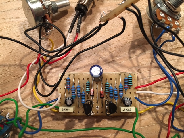
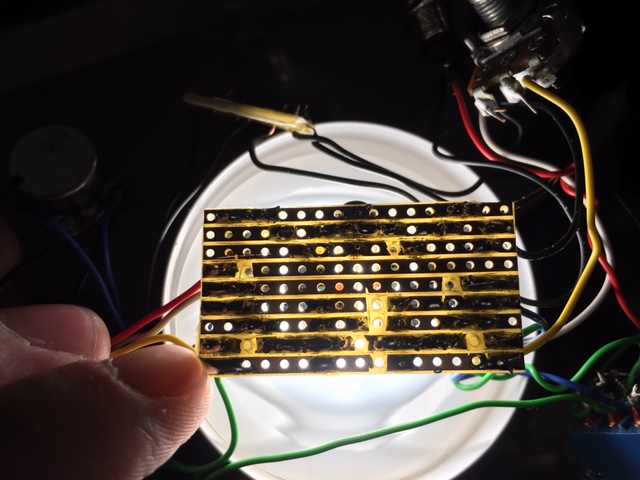
So.. I have wired it up as per layout. Triple checked every component, Knifed it swapped transistors, reflowed solder but no luck volume wise. Switch one gets up to unity with gain fully open, just about, but just a scratchy tone. Switch 2 can get around the same volume with the master fully open and the gain fully open. It has the same scratchy tone. Both of them on reduces the volume. If I strum very hard, there is sometimes a pop they suggests there is a lot of power bottled up somewhere (if that makes any sense). I made the same mistake as then, forgot the 100r resistor at first. This would only mean the 9v is not going anywhere so I don't think that did any damage. The voltages I have are: 1: D 4.47 G 0.76 S 0.0 2: D 4.67 G 0.73 S 0.11   I did one stupid thing while hooking it up to my test rig.. I connected the 9v from the powersupply to the output wire instead of the 9v. Im using other transistors than that time. The traces look a bit dirty, but that's from the knifing. I had hoped I would be able to make this work after 3 or 4 years, but apparently not. Which stupid mistake am I making? Hope anyone has an idea! |
|
Your 100k resistors appear to be 100R.
|
|
And for what it's worth, from what I can tell, the original unit doesn't have the 100k on the right at all.
The left SHO is just like usual, but on the right SHO the 100k resistor is replaced by the 100k volume pot, so the resistor seems to be included by accident. |
|
Aargh thanks! That's stupid of me.Will change that when I get home. Hope that solves the volume issue!If it's not in the original, I will leave the one on the right out. A shame of the beautiful layout, but this won't be my prettiest build anyway :)
|
|
If you like the symmetry of the layout with the resistor included, you can just add a cut between the resistor and the volume pot. That will take it out of the circuit completely, but leave the look of the layout as it is.
|
|
Ah, it's ok. It's a great symetry, and I have the most respect for making it like that, but I won't open the pedal up, so I'm ok with leaving it out :)
|
|
In reply to this post by induction
It occurs to me that one way pedal builders could protect their circuit designs without gooping would be to make circuit board with about 10 or more "fake" parts (parts that are not attached to the actual circuit)...

|
|
haha, didn't Walrus Audio did something like that with the Mayflower with a Timmy design? I could be waaay off but remeber something like that, adding an opamp.
|
|
In reply to this post by Frank_NH
As far as I'm aware, this has already been done, though I can't remember the name of the guilty company or circuit.
I'm sure I ploughed through a long thread on FSB once, where they tried to reverse engineer a pedal from gutshots and had to deal with a load of "dead end" components. EDIT: Ha, Marbles beat me to it. I can't remember if you is right about it being the Mayflower, but mentioning a Timmy variant does ring a bell. |
|
Im not 100% sure, may be making false accusations here haha.
Got it to work, thanks guys! Good eye spotting the noob 100r/k mistake :) Have been throwing some wrenches at walls though... Pots.. Grrr. You tighten them, but after putting on the knob, the whole pot turns, straining the wires. So you tighten it a little more, and... The damn thread breaks or something and you can't tighten it anymore, it's super loose. Whole damn thing taken apart again to change 2 pots. Man I was grumpy... Works great though, although when both sides are fully open, turning a gain knob feels at certain positions like the transistor needs to adjust to the situation half a second. So there is a small pause in the sweep if that makes sense. Works well enough though!  |
|
This post was updated on .
That's exactly what happens, the gain control alters the dc bias on the mosfet, and it takes a split second for the transistor to re-adjust to the new bias and start passing signal: Perfectly normal for this design. Other gain pot arrangements utilising the source/emitter (e.g. fuzzface gain pot) only alter the "AC bias" because they incorporate a capacitor to ground, so do not crackle or cut out intermittently. For future reference, you can use a fuzzface gain pot on the SHO but you lose the "impedance altering" effect of the stock gain pot: That is, as you increase the gain by reducing the source resistance, the input impedance drops so the glassy high impedance boost doesn't get too "ice-picky" bright at higher boost levels. |
«
Return to Debugging
|
1 view|%1 views
| Free forum by Nabble | Edit this page |

