biasing j201s

classic Classic list List threaded Threaded
18 messages Options
Reply | Threaded
Open this post in threaded view
|

biasing j201s

kirshman
So, I'm trying to get a rog umble going, and it just has whiny grainy whistle when on but i'm not playing, and it makes a really metallic farty noise when I am playing.  replaced 201's, went back and knifed the openings multiple times,  looked at the board over and over and can't figure out where i went wrong, so I just want to make sure i biased these correctly.  I powered the pedal up (using a battery), turned the master and volume all the way up, and set the drain pins to 4.5ish.  (ranged from 4.5 to 4.53) I didn't have any cords plugged into it, should i have?  Just seeing if this is the correct way to do this.  Thanks!
Reply | Threaded
Open this post in threaded view
|

Re: biasing j201s

fenderguy79
Hi Kirshman,
4.5V at the drain is correct.  You don't need to have the input/output plugged in to bias.
Do you have an audio probe?
If so I would check the audio at the input, then at each drain to see where it stops.
Hope this helps!
Reply | Threaded
Open this post in threaded view
|

Re: biasing j201s

Frank_NH
In reply to this post by kirshman
Post some pictures of your build.  It does sound like your JFETS may be misbiased, but it could also be something entirely unrelated.  Also, measure the gate and source voltages - that may help us as well.

Reply | Threaded
Open this post in threaded view
|

Re: biasing j201s

motterpaul
In reply to this post by kirshman
I have found with some circuits that some pots may somehow stop you from hearing your circuit until the J201s are biased more correctly.

Try putting all pots in the middle first. Then try putting all J201 trimpots in the middle. If you keep experimenting in this way - often you will finally hear something. But just one incorrect trim or pot setting can stop you from hearing anything.
Reply | Threaded
Open this post in threaded view
|

Re: biasing j201s

kirshman
So, sorry for being unclear.  I can hear consistent tone coming out of the pedal when I'm playing, there's just a metallic farty noise on top of it.  It get's a little better at lower gain, but not good,  there is also a high pitch whine when I'm not playing anything especially when the treble knob is up higher. Please forgive the mess in these pictures, it's been moved, spun, and everything else now, as well as re-knifed several times and reflowed once.  
The 201's are
middle left       bottom center    middle right    top right
G  0                           -.01              0                0
S  .37                         .55              .32             .31
D  4.47                      4.47            4.47          4.48

That bottom center one looks off compared to the others, but I'm not sure what to do about it.  Thanks for all of your help!
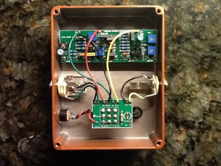
20150225_103814.jpg

20150225_103949.jpg
Reply | Threaded
Open this post in threaded view
|

Re: biasing j201s

kirshman
So the spacing of that looked real good on my computer, but when i looked at it on my phone it was a pile of garbage. so the voltages of the 201's are: middle left g 0  s .37  d 4.47 , bottom center  g -.01  s .55 d 4.47 , middle right g 0  s  .32  d 4.47 , top right  g 0  s .31  d 4.48.  So the bottom center one looks different, but i'm not real sure what do because of that.  Any and all help is much appreciated!
Reply | Threaded
Open this post in threaded view
|

Re: biasing j201s

Frank_NH
Those JFET source voltages look low to me.  Check the polarity of the tantalum caps and make sure they are consistent with the electros shown on the original layout.  Are those small caps (pF range) tantalums as well?
Reply | Threaded
Open this post in threaded view
|

Re: biasing j201s

kirshman
Nope, the pf ranges are multilayer ceramic.  I did just check, and the tantalums are the right direction as well.
Reply | Threaded
Open this post in threaded view
|

Re: biasing j201s

Frank_NH
OK.  I have built an Umble (using a PCB) and can check my voltages when I get a chance.  You may want to do the usual things (i.e. audio probe, reflow solder joints, check continuity).  I didn't go through your layout but at first glance I didn't notice anything unusual.
Reply | Threaded
Open this post in threaded view
|

Re: biasing j201s

kirshman
thanks, for your help man.  I'd love to see your voltages too!
Reply | Threaded
Open this post in threaded view
|

Re: biasing j201s

Frank_NH
I checked my voltages tonight, and actually yours may be OK.  Here's what I got (I biased my drains to 5 V):

Source: 9.6v  (wall wart)
All gates have negligible voltage:

Q1: D = 5V, S = 0.18V
Q2: D = 5V, S = 0.22V
Q3: D = 5V, S = 0.18V
Q4: D = 5V, S = 0.20V

Here's my Umble (from a TH Customs PCB):

Reply | Threaded
Open this post in threaded view
|

Re: biasing j201s

kirshman
Well so much for simple huh, I'll keep checking.  thanks for all your help!
Reply | Threaded
Open this post in threaded view
|

Re: biasing j201s

motterpaul
FWIW: I found the Umble to be one of the most frustrating builds here. I could also get sound but not "good" sound for a very long time.

I suggest you double-check all of your resistor values - along with all the other usual things. But that fact that you getting sound but just not the right sound suggests you circuit is close but a value might be off.

Then I suggest an audio probe - because if your voltages are okay it is more likely in your audio signal path.

Also - I don't see the 22k resistor upper right (could be there, but I don't see it)
Reply | Threaded
Open this post in threaded view
|

Re: biasing j201s

motterpaul
I'm adding post instead of editing so you see it. I rotated your pic so it would match the diagram orientation, so I am referring to diagram orientation.

There is something that looks odd in the upper right hand corner to the right of the 220K with the links of the 330 pF, 47 pF. It looks like an extra wire coming from the pot - I don't understand what I am seeing there.
Reply | Threaded
Open this post in threaded view
|

Re: biasing j201s

kirshman
I'm not sure what you're referring to?  There of cap has a bend in the leg cause its a 5mm multi.  Or are you talking about the red wire coming out beside the trimpot? That's the 9v wire.
Reply | Threaded
Open this post in threaded view
|

Re: biasing j201s

motterpaul
I am talking about the wire that goes into the board right where the two white lines cross adjacent to the 220K resistor in your picture. If your picture was oriented (turned CCW 90-degrees) the same way as the diagram it would be in the the upper right corner of the circuit layout.

I see that wire in your circuit, but not in the diagram. it could just be a twisted wire off the 330 pF, but it's hard to tell.

Did you have any luck - do any other troubleshooting?
Reply | Threaded
Open this post in threaded view
|

Re: biasing j201s

kirshman
Yeah, that's just a bend in the 330pf cap wire, it doesn't actually go into the board.  (if we're looking at the same thing :)) I have looked through all the values, and knifed and set the drains to slightly different values, and just can't get this thing going.  I do have an audio probe, because I made test box 2.0, but i'm still pretty new to this and don't know how to use it very well.  Lot's of videos on how to make one, not really how to use one.  Got a link?
Reply | Threaded
Open this post in threaded view
|

Re: biasing j201s

motterpaul
Audio probe. I assume you have a 1/4" jack coming off the circuit that has a cable connected to an amp so you can hear the output?

http://diy-fever.com/misc/audio-probe/ - here is a link on how to build one. The cap is there for protection in case you hit some +9v - which is a good idea - some amps can get problems if they get voltage like that in the input.

Make a probe and connect the clip to the + (tip) of the amplifier IN jack (leave the cable to amp connected and keep the ground on that jack grounded as normal) - then just take your probe and start probing. Start at the circuit input and see where it connects to follow the audio path .... include your pots and both sides of resistors.

When you run into a point where the sound deteriorates start to look for issues with your build. It could be right at that spot, or it could be the next component, but it will probably be in that area.