diefet capacitor 100uf or 10uf?

classic Classic list List threaded Threaded
5 messages Options
Reply | Threaded
Open this post in threaded view
|

diefet capacitor 100uf or 10uf?

marcus262
Hi,
I have a question regarding some of the capacitors on diefet schematic.

Veroboard has 3x 100uf caps and 2x 10uf caps,
but the schematic that it was built on has 2x100uf caps and 3x10uf caps.
So I am wondering if that is a mistake? Could someone help.

http://tagboardeffects.blogspot.hr/2014/06/diefet-diezel-vh4s-simulator.html
http://techniguitare.com/forum/ressources/image/1663


Reply | Threaded
Open this post in threaded view
|

Re: diefet capacitor 100uf or 10uf?

Ciaran Haslett
Not a mistake.  The charge pump on the schem is a 1044.  The charge pump on the layout is a 7660.  Those values are correct for their given care pumps.  Nothing to worry about.  The end result is 18 volts.
Reply | Threaded
Open this post in threaded view
|

Re: diefet capacitor 100uf or 10uf?

marcus262
Thank you very much.
I am starting to collect all the parts and this has been bugging me all along.

thanks again.
Reply | Threaded
Open this post in threaded view
|

Re: diefet capacitor 100uf or 10uf?

Frank_NH
This post was updated on .
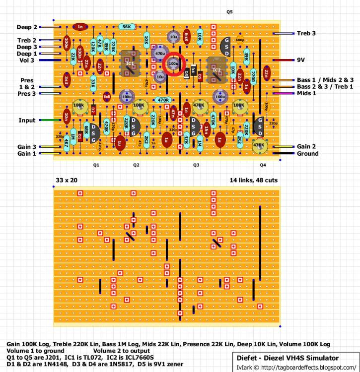
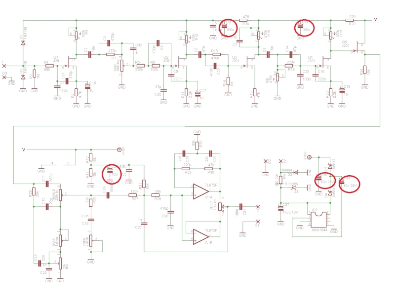
The layout does deviate a little from the schematic in other ways, e.g. the large 470 uF should have a small resistor ahead of it and some diodes, presumably to remove ripple from the incoming 9V power.  As it stands, the charge pump design should work fine.  If you are ever wondering, you can consult the data sheets for the charge pumps, which have the typical application schematics for a voltage doubler, split voltage supply, etc.

icl7660s:  http://www.intersil.com/content/dam/intersil/documents/icl7/icl7660s-a.pdf
max1044: http://pdfserv.maximintegrated.com/en/ds/ICL7660-MAX1044.pdf
tc1044: http://ww1.microchip.com/downloads/en/DeviceDoc/21348a.pdf 
Reply | Threaded
Open this post in threaded view
|

Re: diefet capacitor 100uf or 10uf?

marcus262

thanks for the info.
yes, I noticed that too about the extra diodes and the resistor,
but the veroboard layout is verified and those who build it say that it works,
so guess i should just go with that.