diefet: need fresh eyes...
|
Hi guys,
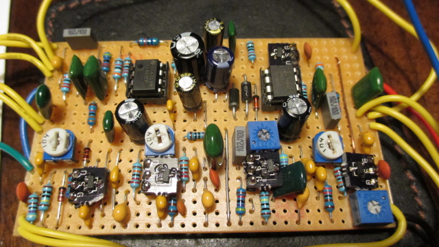
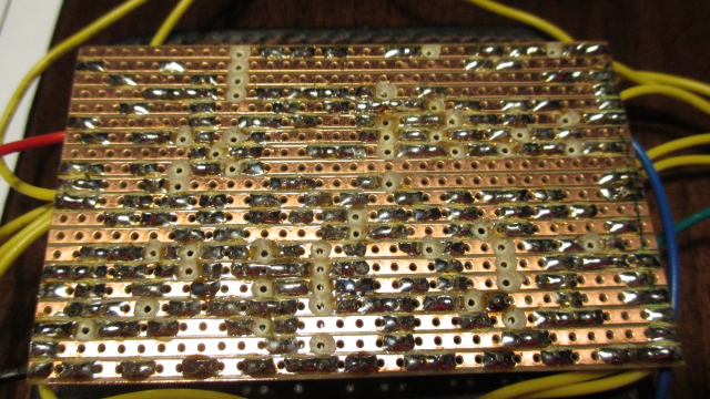
I've been a bit stuck for the last 2 days... The effect is there (and the controls seem to work) but there's very little output (lots of gain and all but very little volume). I've looked at it every which way and still can't find anything. I've checked the usual to no avail: blade between the tracks, values, spacing, etc... Here are a few pics. For those who will be kind enough to take a good look: please let me know if you see anything that makes no sense. Thanks a million, Phil   |
|
Administrator
|
hey phil. i'm not 100% sure, but i got 2 things it might be. 1 bad jfet/not biased right, or i know you checked, but i had the same problem when i built the wampler ecstasy and i had the wrong cap near the output of the effect which caused me to have nearly half the volume it should have. also, i assume you checked check for a cold solder joints, right?
|
|
I would use an audio probe to trace the signal from volume 3 towards the output of the op amp. When you detect a jump in volume, there you go! If that doesn't do it, then it could be a bad component...
|
|
In reply to this post by Surgeon
All looks pretty nice and neat to me. Rocket's suggestions are sound, so try those first.
If it was me building that I would by re-checking all my cuts and links again. (That's where my dyslexia shows itself most.) Also I've never used those surface mount transistor adapter boards before, so I'd be making sure that they are working ok. Don't give up though, but worth leaving it for a while. Put it aside for a week or two, then have another try. |
|
Administrator
|
Measure all the JFET and IC voltages, that will always give the best clue of where the problem may be. If everything looks good from that then I'd look at using an audio probe as has been suggested and follow the schematic. That will show you exactly where the volume is dropping off and make it relatively simple to diagnose
|
|
The two biggest problems I encounter with my builds are solder bridges and cold solder joints. The only way to detect and confirm them is to use the continuity check function on your DVM (mine beeps when continuity is detected). For solder bridges, check all the track cuts and adjacent tracks, with the vero layout as a reference. You should also check the jumpered connections to make sure they work. For cold solder joints, I check these by holding one probe on the solder joint and the other on an exposed lead on the other side of the board (a small vice is handy for holding the board while you do this). If you detect a lack of continuity (cold joint) you can easily reflow the solder with a hot iron and check again. This can be very time consuming, but I've fixed several builds now by examining the solder joints one by one. Good luck!
|
|
Thank you for all your comments gentlemen.
I was hoping it was something obvious but if it all seems in order to you... Reverse probing will definitely be done soon, I just thought I'd post the pics in the meantime. No solder bridges anywhere (checked, scraped and rechecked). I've never had one cold solder joint in over 50 pedals but there's always a first... I'll have to check. Voltages: is there any place I can get the adequate working voltages? With the charge pump I'm assuming it shouldn't be 4.5v on the drain no? Also, the best sounding spot for all trimmable jfets is on the far right... never had a bad jfet in my smds but it may be time to recheck. Maybe use a few through-hole to compare... that's the sucky thing about the smd ones: with the adaptor pins they don't fit in sockets. |
|
Ok, help me understand this one please.
Probing starting at the output showed this: when I reach the 1n cap on the uppermost left corner I get the very faint signal on its left side and a very strong signal on its right side. However, the cap isn't bad (took it out, measured it, put another one in, all the same), no bridges between the first and second traces, all seems perfectly good... the deep pot looks ok too. Any ideas? I usually resolve these things quickly but right now I must be tired or something 'cause I can't seem to figure it out... thanks again! |
|
Administrator
|
No you start at the input and see where the signal is dropping. It's late and I'm going to bed but I'll post the order of components to check through tomorrow
|
|
Thanks Mark, I'm aware of that but I thougjt I'd try to find out where the signal goes up instead since the efffect works but with very little output.
the list will be appreciated and I'll try to find a schematic (or if you could provide one?) As usual, your help and time are most appreciated.. cheers mate! |
|
OK - I had a look at the schematic here:
Diefet Schematic It appears that the unlisted cap bridging the input and output of the op amp stage in the schematic is the 1 nF cap where your volume drop occurs. This makes me suspect the TL072 op amp. Check the output voltages at pins 1 and 7. In fact, check all the voltages. It's possible the chip is bad. Note that the 100 nF cap goes directly to volume 3 in the vero whereas the schematic has some pre-output filtering going on (in addition to a 1 nF treble bleed cap bridging Volume lugs 2 and 3). |
|
thanks for the reply and schematic link frank. I'll start my work from these...
Cheers! |
|
One more note. The op amp is expecting +12 volts - it is possible that the voltage provided by the ICL7660 chip is off, so check pin 8 on the TL072 for the required voltage.
|
|
Final diagnosis: bad tl072... should've checked this right away but I think it's my first time ever having a bad IC...
I had to increase the trimmer for q1 to 200k in order to bring the drain voltage down to 6v. It's a bit dark sounding isn't it? I'm hoping shielded input/output wire will take care of the tiny bit of squealing I'm hearing on my test-rig. Thank you all for the help! |
|
Hey, glad to hear it's finally working. And don't feel bad about the bum chip. I built the UBE Screamer a while back, and had a similar problem (weak output). I probed the CD4049UBE and I discovered the voltage on the last inverter looked way low. So I ordered some more chips off eBay (25! - hey it was a great deal
 ) and when I popped a new chip in, it fired right up! So you never know. I have always have plenty of ICs on hand so I can substitute if necessary. ) and when I popped a new chip in, it fired right up! So you never know. I have always have plenty of ICs on hand so I can substitute if necessary.
|
|
Administrator
|
awesome. man, so glad it's working now. i had a the same problem with a LM308 chip in the modified rat i built, also the same thing happened with a split n' blend in a pedal the 2n5458 transistors i used were bad. turned out i had an entire batch of 50 turn up shot. thank god i checked them all after i found that out quickly, cause i got a full refund.
|
|
I have bins full of various ICs, built tons of pedals and it's my first time... not bad me thinks... Just wish I had thought of it before I began asking for help...
|
|
Don't be shy about asking for help. As long as we have enough information, someone here can probably figure out approximately what the problem is. Of course, just last night I tried for the last time to get a Runnoffgroove Thor build to work, but I think I'm going to punt. I can recover a good many parts from it and will likely get an available Thor PCB as I really like this overdrive. Sometimes, that's how it goes...
|
|
Tell me about it, I never got my Thor to work perfectly (something about the gain pot...). In the end it ended-up in the trash... one of the 3 pedals I never got working properly (out of so many it's not that bad).
|
«
Return to Open Chat
|
1 view|%1 views
| Free forum by Nabble | Edit this page |

