greer sucker punch help
|
guys, looking for advice.
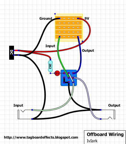
im new to this but what i done is grounded one jack with a cable and thus grounded the other jack via the metal case. i wire all the pots that needs a ground to a jack. in bypass mode the guitar works, when i push the switch the led come on but initially no sound, with playing about the most i can get out of it is a quieter clean sound that can manipulated slight by using the pedal volume pot. all connections seem ok, any ideas? |
|
Administrator
|
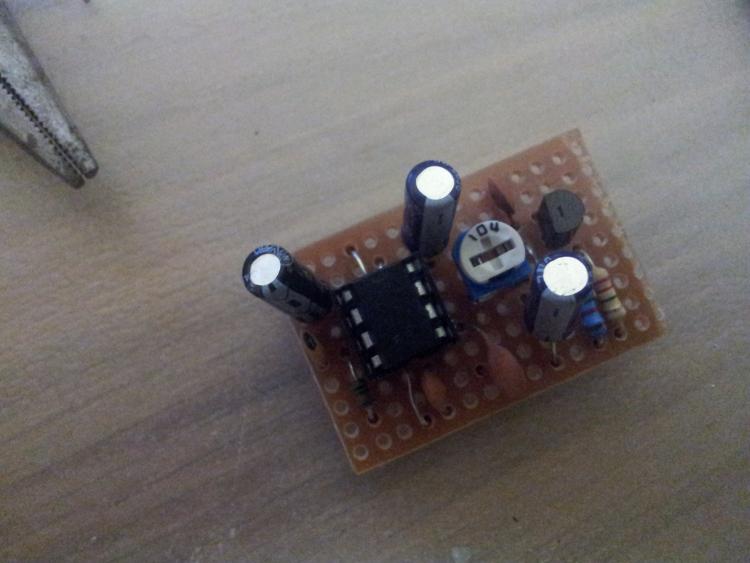
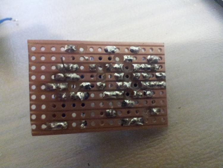
Can you post pictures of the top and bottom of the board, and can you get voltages on the IC and the JFET? Without those it will be hard to really give something other then general debugging advice. My assumption would be that there may be solder bridge somewhere, so run a knife between the copper strips, and make sure there's nothing there.
|
|
rocket, cheers for the reply. When im back in from work i will check and upload. so far i have checked for bridges with the continuity checker on the meter, checked for cold joints and made sure round connections are sound. i looked to see if there was a guide ic voltage to check against but didnt see it.
i will get this tonight. |
|
In reply to this post by mizzion
ic
1 1.3 2 0 3 0.3 4 0 5 1.3 6 4.74 7 9.44 8 0.8 jfet d 9.43 s 0.9 g 0 |
|
In reply to this post by mizzion
Another thought. This is only my second pedal so wasnt sure if ibwas right in taking the connection from tone 2 too output on the switch (using off board wiring on here)
|
|
In reply to this post by mizzion
Does anyone have a suggestion or know where I could find a list of desired pinout results. Been searching but found nothing
|
|
Just make sure everything that needs to be grounded is connected together - jack outputs, circuit board, DC input, foot switch.
In tone 2 to output - that should go to the foot switch to the post that joins "1/4-inch jack output +" when the switch is on. Upper right hand corner of foot switch  |
|
This post was updated on .
In reply to this post by mizzion
To help eliminate issues I rebuilt the board. Not added offboard wires yet
 
|
|
I think I can spot two major errors on here Mizzion.
#1. The 47uF cap on the left of the board - the bottom leg needs to come down one row, from pin1 to pin2 on the IC. #2. Column 9 needs two cuts - one between the lower legs of the trimpot, and one just below that. In reference to your previous post, yes, tone two to switch output. |
|
thanks for the reply guys, good news is there hasn’t been feedback on super bad soldering or the wrong components etc, however after reading this I cross referenced the positioning and cuts from my first build and the errors on here where not on the original build......... will address this tonight and try the off board wiring from scratch. I wondering if I would be better just building at the weekend etc when im not tired after work :P
|
|
One thing I noticed is that it is hard to see where your cuts are when you look at the non-copper side of your perfboard - where you place your components.
If you mark them with a sharpie or (even better) drill them out from the plain side with a small drill so you can see where the cuts will go on the copper side - then it makes using the cuts as reference points on the component side much easier - That way you can just look at the component side and see that all the cuts are in the right place and that the components are placed accordingly. I think this would make things easier for you and for us to see your work. |
|
In reply to this post by mizzion
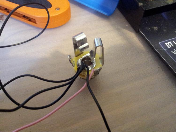
Just wanted to check I had this right. Pink wire should be my tip of input jack and the black is the ground wires

|
|
Yep, your grounds go to the sleeve (the ring in the middle) and the input or output wire will connect to the tip, which looks to be as you have it

|
|
Administrator
|
Btw, are you planning on hooking up a battery snap? If not you don't need to use the stereo jack, you can use mono jacks instead. Which is great, because they are cheaper and you don't need to deal with the extra lug. The reason for using a stereo jack is that it acts as a switch. when a plug is inserted it allows the battery to discharge into the circuit, otherwise the battery is disconnected so it doesn't drain when not in use.
|
|
hey bud. gonna use a battery sap which was added after that pic. loosing the will to live, redone wiring , switch, jacks , checked for poor connections or unwanted bridge and it does nothing. bypass works thats it

|
|
also the ic now reads
1 8.8 2 8.15 3 7.5 4 8.15 5 0.5 6 9.5 7 8.8 8 8.8 
|
|
Do you have a breadboard?
Wire up the DC jack and connect it to the breadboard rails for +9 and ground. Your effect should have four wires +9, ground, input and output. Run everything that is supposed to be ground to the rails for ground on the breadboard including the guitar jacks, circuit, etc. Connect the effect +9 to the breadboard +9 rail. Then just wire up the guitar and amp jacks and put "tip" into separate breadboard slots connected to the effect's "input" to guitar jack (tip) and "output" to amp jack (tip). This way it is easier to check that the circuit works before you worry about getting all the grounding right. |
|
sadly i dont yet.
until now i have been testing variation of battery power. just hooked the dc jack up n it just hums. i checked the voltage and polarity of the universal power supply first |
|
In reply to this post by mizzion
http://www.beavisaudio.com/techpages/PedalPower/
Be sure to read this carefully about jacks and batteries together. You have to read it (not skim it) the key is that the DC jack pins change when a plug is inserted. |
|
This post was updated on .
hey bud cheers for this. i read similar else where too.
i can confirm that with the jack in my board is receiving the 9 v with my battery in , guitar cable in and jack out the board gets 9 v with my battery in , guitar cable in and jack in the board gets 0 v with my battery in , guitar cable out and jack out the board gets 0 v also if i connect my meter to board 9v and neg too tone 2 i get 9v if i do board 9v too the switch out (top right) i get 9v if i do board 9v too switch output jack (far right middle) it drops too 3.16 v switch down switch engaged completes as 9v :/ also jfet reading d 0.01 s 9.15 g 7.8 |
«
Return to Open Chat
|
1 view|%1 views
| Free forum by Nabble | Edit this page |

