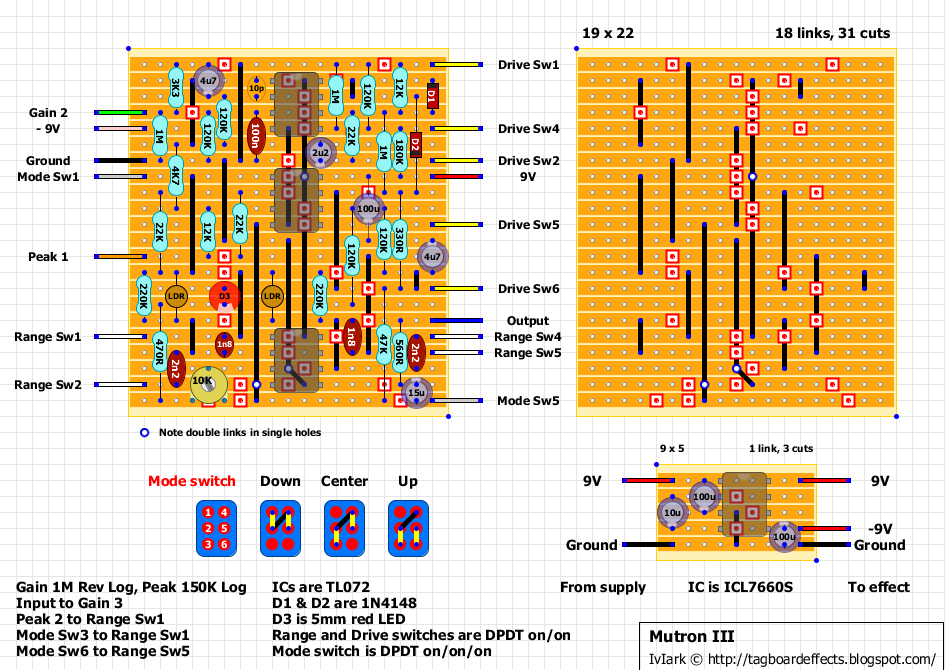
hey guys,
curious if mark or somebody could point me to a proper schematic for the mutron phasor II
mark drew up years ago?
this one:

i checked voltages without the chips in it, got what i expected to be normal, but when i fired it up the charge pump just got super hot and the first led glowed super bright and then i imagine burned out.
voltages all seem reasonable other than the center chip of the bottom row, i'm getting the same voltage on pins 1 and 2, about 9.5 v which is way too high i think, and indicative of a short... but i can't seem to find one, and this vero, tho brilliantly crafted and executed is damn near impossible to follow linearly to debug without a schem....
also, whats the deal with the blinky indicator? lights up solid, but where is the cathode/band supposed to go, ground, right? shouldn't matter if its ground on the board <mid point between +/- voltages> or , well, actual ground. i star grounded everything to the input jack sleeve like usual, perhaps there's something i missed?
somebody buy the old pink dude a clue?
of course i can post voltages etc, but with the right schematic, it shouldn't be necessary. i am sure its something really dumb. ;)
thanks guys
peace!
PjP
wha, me worry?