not really a pedal... but useful for musicians. Cmoy headphone amp for in-ear monitor.

not really a pedal... but useful for musicians. Cmoy headphone amp for in-ear monitor.

|
How about a very compact layout for a Cmoy style headphone amp for use as a wired in ear monitor solution. Maybe with an on board voltage doubler to get the most out of a OPA2134. I have found a couple vero plans out there but they aren't very efficient on real estate. Ideally, this would fit in a small lightweight enclosure for an unobtrusive belt-pack. I looked at the head phone amp pedal posted here but being more hi-fi, this should be able to do the mix required of an in ear better, I think.
|
Re: not really a pedal... but useful for musicians. Cmoy headphone amp for in-ear monitor.
|
|
Well, first off I'm absolutely brand spanking new to this. I have no electronics background. Only 1 pedal build under my belt (two circuits one pedal, a SHOD with a Micro Amp boost circuit clone, and it sounds sweet to me). But, I've always figured it's best to take responsibility for my own ideas...
All that is to say don't beat up on me for stupid mistakes, but if any of you could look over below and let me know if it looks like I'm on the right track. The idea is to provide close to 18v to a OPA2134 based CMOY headphone Amp to get the best sound available and run it through a hard limiter circuit to clip damaging volumes and protect the musician from runaway feedback, a dropped mic, whatever. I chose to build it on 3 separate boards to allow for stacking them tightly in a small project enclosure to keep the whole thing compact and wearable. I have credited my sources on the drawing... 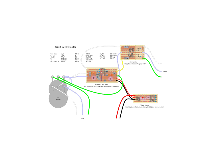
|
Re: not really a pedal... but useful for musicians. Cmoy headphone amp for in-ear monitor.
|
|
Here is a link for better viewing (hopefully).
https://drive.google.com/file/d/0B_Sh_vDhJkMqbVRDanpNNzEzN28/edit?usp=sharing |
|
|
This post was updated on .
Good first attempt.
First, may I suggest that you label all of your wires. (Left signal, right signal, ground or Vref, what voltage are you feeding the charge pump, and what voltage are you getting out of it.) There are a few small problems with the veros, and a few more with the design. The design flaws mostly stem from how the grounds are adapted when you convert from a schematic with a bipolar power supply to a layout with unipolar power. (Don't feel bad. You're not just attempting to make a vero, you're actually to design work here. Some mistakes are inevitable. That's how you learn.) On the charge pump: Your diodes are reversed. On the amp: 1. Your pots are wired backwards. 2. I assume that your source signal has no DC offset (biased at 0V). If so, then lug 1 (or lug 3 with your wiring as shown) should go to ground, not Vref as you have it. Otherwise, you're feeding DC to the ground of your audio source, which will cause pops, bleed current, and (worst case scenario) possibly damage the audio source circuit. 3. The lower leg of R3 should be on row E, not row F. On the Limiter: 1. Your trimmers aren't in the circuit. The outputs should be taken from rows B and F, not A and G. 2. Your output signal is DC biased. This will push DC current through your headphones, and will cause popping when the circuit is turned on and off. I think the simplest solution would be to replace the voltage doubler with a voltage inverter. Then you can use the schematic as written instead of adapting it (I would still consider AC coupling the output, though), you can get rid of the bias resistors (R1 and R2). If you prefer, you can keep the voltage doubler, but then you have to use Vref as virtual ground only where there is DC offset in the signal, and use 'true' ground otherwise. And you definitely have to AC couple the output. Either way will work. Edit: Your hard limiting circuit will reduce your maximum output to about 1.4 V peak-to-peak, which kind of defeats the purpose of the amplifier in the first place. You'll probably want to string a few diodes together in each direction to allow for a larger voltage swing. Maybe also use leds instead. Start by figuring out what your maximum acceptable voltage swing is, then look up (or better yet, measure) the Vf on your diodes/leds, and string together enough of them to give you the correct threshold. |
Re: not really a pedal... but useful for musicians. Cmoy headphone amp for in-ear monitor.
|
|
Obviously I have a lot of work to do and I really appreciate your input. I will label better and fix the mistakes on the veros (boy those look really dumb once they're pointed out, but it's a first draft, I guess).
I wondered about using a voltage inverter instead of a doubler as it was clear that the CMOY was splitting the voltage. But only being used to thinking in "+voltage and ground" I'm not really sure how to approach hooking up an inverter. It looks to me like row "E" on the CMOY is the "virtual ground" would I be able to ground that (to battery negative and ground on input, output, and chassis?) and then run +9 to F and -9 to G? If that's the case it make sense to me that I could drop R1&2... I have to admit to not really knowing what you mean by AC coupling the output (I will do the reading to figure it out, but if it's simple enough for you to clarify that would help.) On the Limiter I planned on breadboarding it and/or socketing the diodes to experiment with getting the right tradeoff between high enough volume (for the headphones used) and safety for the user. I had read that using LEDS make for a more pleasant sounding clipping circuit because of the harmonics they create so that is definitely an option (socketing makes that easy to try). This probably going to be used with a couple of 32ohm earbud type headphones so 1.4v might be plenty loud, but maybe not. Edit: could this inverter be used? http://tagboardeffects.blogspot.com/2012/05/negative-voltage-inverter.html |
|
|
Exactly. AC coupling is when you feed a signal through a capacitor before it reaches the next stage. Simplified ideal capacitors look like perfect resistors to the low frequency (including DC) voltage signals, but look like perfect conductors to high frequencies. (For a less simplified explanation, read this.) For example, the output of an op-amp with +9V and 0V rails, will usually be biased at 4.5V. If that signal goes through a capacitor, the 4.5V DC gets removed, and only the audio signal remains. (Of course, if the capacitor is small-valued, the signal loses bass as well.) With DC coupling, the signal doesn't go through a cap, so the DC bias is still present. This approach is common when the next stage requires the same biasing as the previous one. Instead of stripping out the DC with a cap, and then adding it back in again with bias resistors, you just directly couple the biased output of one stage to the input of the next. There are times for each approach, but as a general principle of good design, you want the output of any modular circuit to be biased to 0V. So you put a cap and a pulldown resistor (1M or 2M, should do be fine) before the output. The size of the cap depends on the expected input impedance of whatever you plug into it. The cap, and the parallel impedance of the pulldown and the headphones (for instance) form a hi-pass filter. The corner frequency is fc = 1/(2*pi*RC), where C is the cap value, and R is the parallel impedance of the pulldown and the headphones. Calculate R, choose the lowest frequency you want to let pass, then solve for C. Excellent plan. Just what I would suggest. Don't believe the hype. For our purposes, the only difference between different diodes, including leds, is the forward voltage (Vf). (Technically, there is also the knee, which refers to sharpness of clipping. Silicon clips harder than germanium. 'Harder' means that anything above Vf becomes Vf. A 'softer knee' means that instead of a sharp contrast between clipped and un-clipped, there is a very small band around Vf that compresses instead of clips. Look here for a cartoon example. Whether you can hear the difference is something people will argue about for hours at a time.) Germanium diodes usually have a Vf around 0.2-0.3V, Silicon diodes are usually somewhere around 0.6-0.7V, leds are usually 1.0-4.0V, depending on type and color. They vary among devices, so you can check the datasheets for a ballpark figure, but to be sure what yours are you have to measure them (with a diode tester on a DMM, for example). There is no inherent sound difference between 1N914's and led's. Both are silicon, so the knee is sharp. The harmonics depend entirely on the relative size of the signal and Vf. A louder signal and a higher Vf will sound exactly the same (although louder) as a quieter signal and a lower Vf, as long as the ratio between the signal size and Vf is the same. Absolutely. |
Re: not really a pedal... but useful for musicians. Cmoy headphone amp for in-ear monitor.
|
|
Induction, first let me say thanks for all your help on this. I don't know where you are in the world, but if I ever get there, I owe you a beer or whatever your beverage of choice is.
I think I have most of the recommended changes in here. I welcome any additional input from the community. I left out AC coupling for a couple reasons (no pun there...) 1.) I assume getting away from Vref to an actual ground solves most of the DC bias issue. 2.) The limiter circuit should protect the wearer (and headphones) from overly loud pops and keep any of these to minor annoyances at startup or shutdown. 3.) As I was reading to try to understand the principal and calculations of the resistor and cap values, I learned that there is a cost soundwise (namely a loss in bass response) and with all things being equal I'm hoping this will be as transparent as possible. If I am completely wrong on any of this please set me straight. Again, thanks! Click the image for higher res... 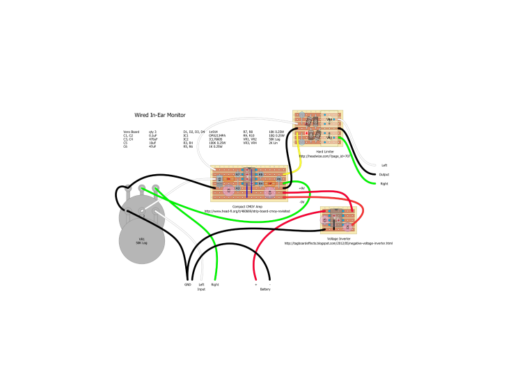
|
|
|
That looks better to me.
Two nitipicks: 1. I'd relabel the 'Output' to 'Ground'. You'll end up with fewer emails from confused customers. The way you handled the input labeling is a good approach. 2. Your trimpots work in opposite directions. VR3 increases resistance when you turn it clockwise. VR4 decreases resistance when you turn it clockwise. Not a big deal, really, and fixing it will ruin the symmetry of the layout. But I'd go for intuitive operation over symmetry, personally. Neither one of these is a big deal. As far as the output caps cutting bass, the idea is to choose output caps that make your corner frequency lower than anything you want to hear coming out of the circuit. If you only strain out frequencies your headphones can't reproduce, you aren't missing anything, you add a little extra protection to your headphones, and you get the warm feeling of knowing you followed good design practice. You can probably get away without the output caps, but you can sometimes find DC in unexpected places. If it shows up on your output, your limiting diodes won't work correctly. |
Re: not really a pedal... but useful for musicians. Cmoy headphone amp for in-ear monitor.
|
|
This post was updated on .
In reply to this post by perpetual-amateur
Built and working.
Made some changes to add a battery monitor and to get the power supply and amp on the same board. Kept the limiter separate because of space and to keep the trimmers accessible. Added trimmers to adjust the gain on the amp to make it adjustable for headphones with different impedance and efficiency. I built this for mono input from a PA aux out but it also would work as a great stereo headphone amp. The battery monitor portion of the circuit is unfinished as I am waiting for an order with some zeners of different voltages to come in... I want the red LED to come on with a couple hours of play time remaining and that will require some testing. The diodes indicated worked well for the most part they matched the peak voltages I measured and seemed to start clipping right at volumes I would consider too loud with 32 ohm headphones (with the gain set at around 6). My drummer buddy used it in practice tonight and said it sounded great, but it started clipping when 2 or more vocalists hit the mics at the same time. That may mean an adjustment needs to be made or it may be that the way they are splitting the signal to him is less than ideal. Time will tell. I am glad I put those trimmers in there now though. Here is the modified design. I'm pretty wiped out right now, so if anyone notices anything I might have messed up as I tweaked this to match the actual build please speak up... 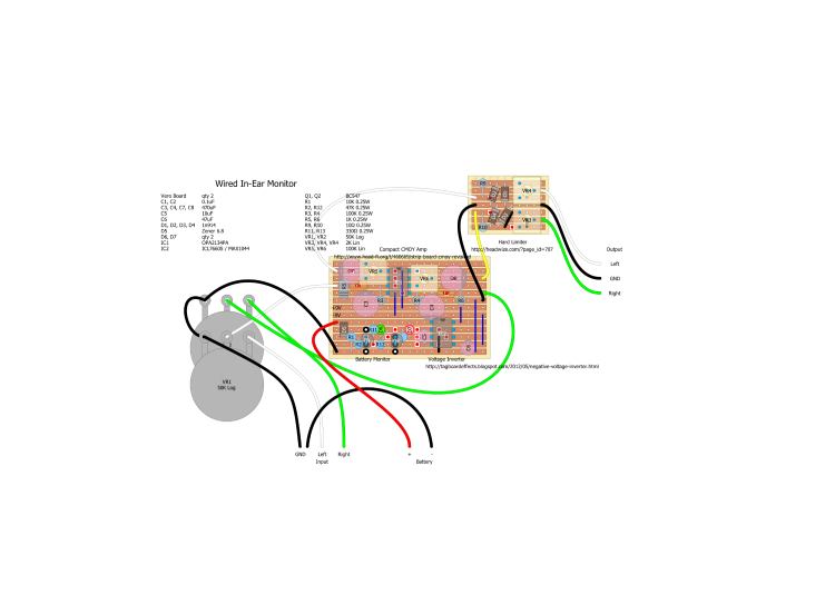 Here's a couple of cell-phone pics of the build...  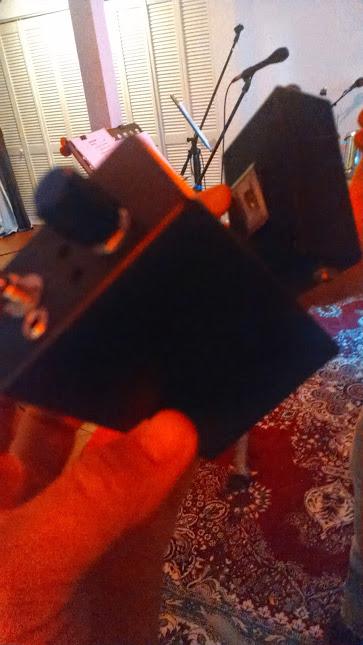 Thanks again to Induction for his expertise and encouragement... |
«
Return to Requests
|
1 view|%1 views
| Free forum by Nabble | Edit this page |