phase issue


|
Hi all!
Im making a Hybrid pedal of a few I've seen on here. It's going to be a JFET splitter running to two individual Fuzz effects and then passive blending back in. My issue is I've been told every time the signal passes a transistor the polarity is flipped. Is this true? if so my 2 sides will be out of phase. What's the best way to flip one side back without overly effecting the sound? Thanks Matt. |
|
|
If your output comes from the collector, the phase will be inverted. If it comes from the emitter, it won't. If your two fuzzes have a different number of transistor stages, it could be a problem. Can't say for sure without knowing which circuits you're talking about. If you do need to flip the phase, a unity-gain inverting op-amp stage, bjt, or jfet amplifier can be used to flip the phase. Beware that some fuzz circuits may sound like poo when fed by a jfet splitter. I'd definitely breadboard this before you build anything. |
|
|
Thanks for the reply. It looks as if the 2 different sides will be out of phase with each other.
How would I go about making a unity game stage? Breadboarding is definitely the first stage for this as I'm sure I'm going to come across some issues but all part of the fun :) Thanks Matt. |
|
|
Sorry I've neglected this for a few days. My wife has been using my computer. I can post from my phone but I can't draw schematics on my phone. I'll see if I can find a link to some schematics that will give you some options.
|
|
|
Here's an inverting buffer made from an op-amp. The inverting buffer is the last image on this page, but read the whole page if you haven't yet.
You'll probably have to do some tweaking to the components, which is why it's good that you're doing this on a breadboard. Remember that the gain is given by R2/R1, and keep in mind that the real value of R1 in that calculation is the sum of the resistor and the output impedance of whatever comes before it. So you may have to calculate that, or adjust the values by ear to get unity. You also have to decide where you are going to flip the phase: before or after one of the fuzz circuits. Depending on the fuzz circuit in question, you might be able to do it within the circuit itself without adding a separate inverting stage. I'd have to see the schematic to be sure. Also remember, as I mentioned before, that some fuzz circuits sound better with a high source impedance, and will sound wrong (or at least different) after a buffer. Since a jfet splitter is just two parallel jfet buffers with the same input, you may need to put some series resistance between the splitter outputs and the fuzz inputs. I'd try 10k, or use a 25k pot wired as a variable resistor and dial in the setting that sounds best. Then remove the pot, measure the resistance, and replace with a fixed resistor. Or maybe you'll find you like it better without the series resistance. Along the same lines, you might want to see if you like the sound when the signals are out of phase. If so, you could have a switch to make the phase flip selectable if you wanted. I guess if it was me (assuming I didn't want to make the phase flip selectable) I'd use a dual op-amp to split the signal instead of the jfet splitter. It's the same general idea as the jfet splitter: feed the signal to two buffers and feed each output separately to one of the fuzz circuits. Set up one of the op-amps as a non-inverting buffer and the other as an inverting buffer. That way you don't need a separate stage just to invert the signal. Alternatively, you could make one of the jfets in the splitter an inverting amplifier (common source amplifier) with unity gain (make the source and drain resistors equal), but then you'd have different output impedances from the two jfet stages. That could be used to your advantage as well, but I get the feeling I may already be overloading you with information and options. With design questions, there are usually dozens of different approaches to achieve your objective, each with its own pros and cons. In the end, you'll have to decide for yourself which path you want to take. Try them all on the breadboard and pick the one you like best in terms of sound, parts count, reliability, cost, etc. |
|
|
Thanks induction! This clears things up nicely. I think I'll have to return to the drawing board for this for now. I had wondered why there's very few, if any split fuzzes with a mixable sound.
I had in mind a Synthy Glitchy kind of fuzz. One side as the devi legend of fuzz ( http://tagboardeffects.blogspot.co.uk/2013/05/devi-ever-legends-of-fuzz.html?m=1) for a more trebley fuzz and another dark bassy fuzz beside it. Mixed together I thought I'd get an interesting analogue synth fuzz effect. A in/out of phase switch I think in these circumstances would actually produce some interesting results. Main concern before I knew about the phasing was that I would just end up with a tonne of Mid fuzz. In that case I was going to use a potentiometer to give the option to divert the signal away from a tranny. This would then be another circuit out of phase so some serious breadboard tinkering is on the cards. You clearly have allot of electronics knowledge, could you recommend a good book that would give me a better rasp of this? ideally university is the answer but that's not quite possible :/= C |
|
|
A lot depends on where you want to go with electronics. If you want to be an EE, then school is a good idea. But if you just want to design and build pedals, you can get all the education you need from the internet, a breadboard, and maybe a copy of The Art of Electronics by Horowitz and Hill. Most academic electronics programs won't focus on old-school analog signal destruction circuits like guitar pedals.
The first thing is to get a good feeling for what the individual components do to electrons: caps, resistors, bjt's, jfet's, mosfets, op-amps, etc. This stuff is pretty basic and you can learn plenty from google and from breadboarding pedals and other circuits from pre-existing schematics. Layouts are great, but you can't learn how a circuit works from a layout. The schematic is the important bit. After you feel confident with components, learn some basic circuits blocks: Emitter followers (aka common collector amplifiers), common emitter amplifiers, op-amps, high-pass filters, low-pass filters, etc. You'll see these circuit blocks over and over. Some of the most common pedals are nothing but common emitter amplifiers - sometimes a single stage, sometimes a few in a row. So read the wikipedia articles and follow as many of the links as you can. There are plenty of other good sources for this stuff on the internet. Your best resources for applying this knowledge to pedal building are freestompboxes (aka fsb) and diystompboxes (aka diysb). Both of those fora are entirely dedicated to the electronics side of stompboxes. Read every thread and spend lots of time with the breadboard. Read the debugging threads and you will see the same problems coming up over and over, and you'll start to get a collection of solutions to the most common problems. You'll learn way more there than you would in school, as far as pedals go. That's where I learned most of what I know. There are plenty of people on those fora that know way more about this stuff than I ever will. Many of the people who design commercial pedals (RG Keen, Brian Wampler, Jack DeVille, Skreddy, and many, many more) post there on a regular basis. Brian Wampler even posted some of his books as pdf downloads on fsb. |
|
|
Thanks Induction. Your insight has been invaluable :)
For futures reference if you were building a pedal with a phase flip switch how would you wire that? The same way as you suggested with a opamp buffer or would you go about it a different way? I have started to read up more so on the subject. I did have a basic electronics knowledge before but this is an entire different level :). Breadboarding the effect gave some Interested results. I think armed with some better knowledge this could be a good project :) Thanks again. Matt. |
|
|
A simple way to include a phase-flip switch would be two wire up two op-amps - one configured as a non-inverting buffer, the other as an inverting buffer. Take the signal you want to flip and connect it to lug 2 of a DPDT on/on switch. The input of the non-inverting buffer goes to lug 1, the input of the inverting buffer goes to 3. The output of the non-inverting buffer goes to 4, the output of the inverting buffer goes to 6. The resulting buffered output comes from lug 5. The switch lugs are labelled like this:
1 4 2 5 3 6 The biasing and coupling (AC or DC) will depend on how you fit it into the circuit. The switch may pop, depending on the biasing and coupling. If so, try to solve that on the breadboard before you build anything permanently. I hope I haven't discouraged you with too much information or design considerations. This could be a cool project. I'm certain it's within your reach with enough patience, and if you work at it, you'll learn tons. Feel free to post design ideas or questions, and I'll offer suggestions if I have any. |
|
|
This post was updated on .
On the contrary your advice has given me some homework and perhaps forced me to gain some knowledge that I should have possessed before hand. Something I cant seem to suss out though is the VR input for the IC. On researching I've gathered what it is but not certain how to achieve. Ive gone for a 100k Resistor off the main 9v then into the Vr connected to another 100k resistor running to ground and that should half the voltage I think? 9v -> 100k -> vr(4.5v) -> 100k -> GRN ?
So taking the inverting buffer from the Musique page I had a quick bash at an inversion vero layout to add to the rest of my pedals board. Omitting the in phase switch and side for now. Would this be correct? 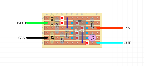 Thanks Matt |
|
|
That looks pretty close, except for the biasing. The Vr setup is actually the first diagram on the musique page. He uses 10k resistors and a 10uF from Vr to ground. That cap is helpful for keeping supply ripple out of the op-amp input.
If you want to use op-amps for the non-inverting buffers as well, then you may want to use a TL074 or a couple of TL072's. Which option you choose is just personal preference, but either way will give you both non-inverting buffers, one inverting buffer, and one extra op-amp. The extra op-amp can be used in one of the fuzz circuits if needed, or can be used to buffer Vref (which isn't absolutely necessary, but certainly won't hurt), or can be left unused (though you should properly terminate the unused op-amp). Alternately, if you only need three op-amps, you could use a TL072 and a TL071. |
|
|
Amazing! Thank you. I'm going to try and breadboard the flip now and I'll return with success or failure.
For now I'm going to try just dropping the circuit at the end of one fuzz and see if it improves the sound. Cheers Matt. |
«
Return to Open Chat
|
1 view|%1 views
| Free forum by Nabble | Edit this page |