philosophers twin


Administrator
|
i've been thinking about compressors a lot. i remembered johnk mentioning that he turned the philosophers twin from the philosophers tone, and all he did was put the Ge OD section on a switch, and bam we get another pedal.
so with that in mind, i found the schematic for the philosophers tone 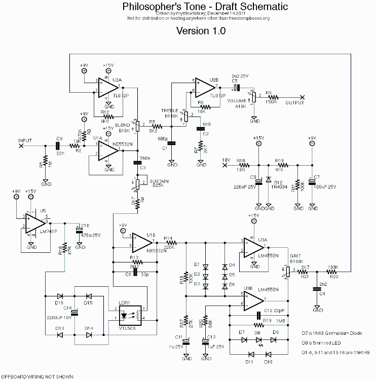 so i'm looking where to place the switch. i'm thinking all we'd need would be an on/off SPST switch between pin 7 of U1B and the 22k resistor or after the 22k resistor into the pin 3 of U3A. what do you guys thing? seems like there's some more talk about compressors again and thought this may be a good build, as long as the switch placement is correct. |
|
|
As far as I can tell, that would eliminate the compression entirely. Skip this part if you just want the answer and not the explanation: -------------------------------------------------------------------------- Here's how I see the schematic: Signal goes into buffer (U1A), and then splits into output signal chain (Blend pot) and compressor sidechain (U1B). U1B is a inverting op-amp, with gain determined by the amount of resistance in the feedback loop. When there is no signal, the gain is high, but when the signal gets high the led in the vactrol lights up, and the vactrol resistance goes down, which decreases the gain in U1B. U5 is just a buffered Vref (+9V) for biasing the LDR/rectifier signal. The output of U1B feeds a pair of non-inverting op-amps (U3A and U3B), the former is just a buffer providing clean output, the latter has clipping diodes in the feedback loop providing 'grit'. Both of these feed into the grit knob (turning the grit knob up or down determines how much of the compressed signal comes from the grit op-amp, and how much from the clean buffer) and then into U2A, which is like a return buffer for the compressed signal (U1A is the send buffer). Both the compressed signal (U2A) and the original input signal (U1A) are fed to the blend knob, which is arranged just like the grit knob: turn it up or down to select between the compressed and uncompressed signals. The way it's drawn implies that the naming is misleading. In a compressor, 'blend' usually implies we are blending the clean signal into the compressed signal, but in this case turning the blend control up gives more of the compressed signal, and turning it down gives more of the uncompressed signal. From there, it goes through some filtering and buffering, and then hits the volume knob and the output. So if you want to put the grit on a switch, you'll still have to let the signal reach U3A, or there won't be any compression. -------------------------------------------------------------------------- To figure out how to do it, you should first decide how you want the switch to work. If you want to toggle between grit at zero and grit at the knob setting, you could try using a SPDT with lug 2 on the R21, lug 1 of the switch on lug 1 of the grit pot, and lug 3 of the switch on lug 2 of the grit pot. Electrically, that's the same thing as instantaneously turning the grit knob all the way down. In one setting the grit knob works normally, in the other it doesn't work at all and the sound is clean. Alternately, you might want to the switch to turn the grit to max, then the knob will work normally in one setting, and in the other setting the pot does nothing and the grit is maxed. If you understood the previous paragraph, then you should be able to figure out how to wire this version, so I'll leave the details as an exercise. I would definitely breadboard this before making a layout. It's possible that there could be a volume shift or popping when you switch the grit on and off. I don't really expect either one of those from looking at the schematic, but it's worth it to check before committing to the design. There are probably other options for the switch behavior that we can discuss if you're interested (different pre-sets, etc.). |
«
Return to Open Chat
|
1 view|%1 views
| Free forum by Nabble | Edit this page |