sunn schematic help

classic Classic list List threaded Threaded
16 messages Options
Reply | Threaded
Open this post in threaded view
|

sunn schematic help

El-even
Hi guys,
after my "déboires" with my pharaoh building
my goal is to create a single channel sunn beta lead preamp and, if it works, make another to complete a sunn pl20 clone without reverb.

i have the sunn schematic manual and need your help to read it
sunn

i'm pretty noob at "technical schem reading"; i rewrote the symbols i don't understand

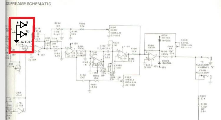
does it means that pins 8-9-10 and 11 of IC 104 (CD4069, 14 lugs IC) go to ground?
or 9-11 to ground and 8-10 not used?

and another question,
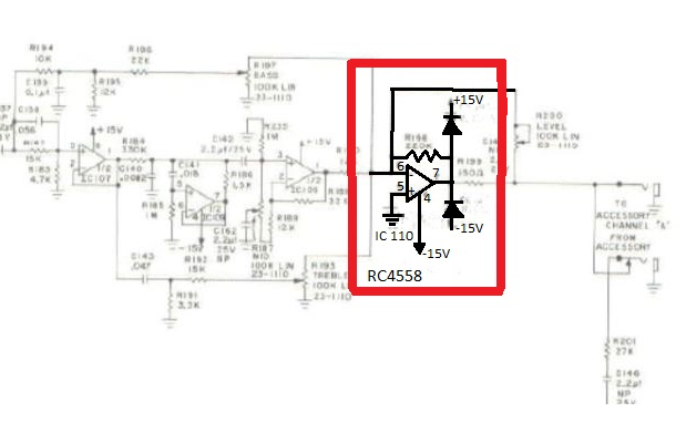
on this schematic, IC's have
> +15v pins, ok with that, simple
> ground pins...simple too
BUT
they have also some -15v pins...what must i do with? and why are they different of ground ones?

Reply | Threaded
Open this post in threaded view
|

Re: sunn schematic help

rocket88
Administrator
Dude. Just had to say, I'm just looking at a vintage sunn tube amp right now and you post this. Really crazy timing. Do you want to rebuilt the actual amp or make it into an amp-in-a-box pedal like the catalinbread stuff?

Also, it's just hard to read that schematic, for me anyways it's really blurry.
Reply | Threaded
Open this post in threaded view
|

Re: sunn schematic help

Silver Blues
About the part you've boxed in red, yes you are correct. It is a good design practice to tie the unused inputs of logic chips to some definite logic level (whether that be a fixed voltage or ground) so since those two are left unused and thus grounded.

The -15V denotes that you need a bipolar power supply. This would require a transformer or inverter so you can get both +15V and -15V for the op-amp. The reason for this is to get a larger output swing, as you technically have 30V of output swing with the midpoint bias at 0V (i.e. ground). Compare to a single power supply at let's say 18V where you have 9V of swing with a midpoint bias at +9V.

You do NOT want to connect the -15V and ground together if you're using a bipolar supply. What you end up doing is connecting the VCC- pin of the op-amp (what we tend to think of as "ground", usually pin 4) to -15V and connecting the bias resistor on the non-inverting input to ground (instead of Vref as you'd usually see it).
Through all the worry and pain we move on
Reply | Threaded
Open this post in threaded view
|

Re: sunn schematic help

El-even
This post was updated on .
@rocket
:)
i don't know now, maybe in big pedal format or in rack3u with all the "fx loops"
i rewrote all the schematic by hand on paper for better readability because yes, this scan is from ancient time and my visual acuity too...

@silver blues

Silver Blues wrote
so since those two are left unused and thus grounded.
because of my poor english i'm not sure understand all; did you mean all pins go to ground?
all "unused" pins needs "thus" grounded?
(the last transistor of the circuit is part of the two channels so, some of his pins are unused.
are they must be grounded or just not soldered?)

i've understand the +/- powering, so this build seems good for my sunn preamp
what do you think about?
http://tagboardeffects.blogspot.fr/2014/01/bipolar-voltage-converter.html

Reply | Threaded
Open this post in threaded view
|

Re: sunn schematic help

Silver Blues
Not quite. THe CD4069 is a CMOS logic IC with six inverters. From what I see in this schematic there are two of those six inverters not used. Whenever this situation arises, it is a good practice to ground the inputs of the unused inverters (so pins 9 and 11) only.

And yes that layout would be great for this application.
Through all the worry and pain we move on
Reply | Threaded
Open this post in threaded view
|

Re: sunn schematic help

El-even
This post was updated on .
ok, thank you very much for the explanations

what can i do with the unused CD4069 output pins in this case the 8 and 10? bending, cutting them...?


same question for the half last RC4558 for the 1,2,3 and 8 pins

?

sorry for these noob questions
Reply | Threaded
Open this post in threaded view
|

Re: sunn schematic help

Silver Blues
You don't have to do anything with those. For CMOS the input being tied down is sufficient, and for op-amps there's no issue with leaving an entire one unused as is. Just solder them in like normal but don't make any connections. You could also use the unused op-amp as a buffer.
Through all the worry and pain we move on
Reply | Threaded
Open this post in threaded view
|

Re: sunn schematic help

El-even
Silver Blues wrote
 You could also use the unused op-amp as a buffer.
interesting...
i will searching more infos for simple opamp buffer

thanks for the help silver blues
Reply | Threaded
Open this post in threaded view
|

Re: sunn schematic help

Silver Blues
Really all you need to to is provide it with the correct bias and tie the inverting input to the output, really really simple. No problem, glad to help.
Through all the worry and pain we move on
Reply | Threaded
Open this post in threaded view
|

Re: sunn schematic help

El-even
hi guys, i think the project is in a bad way

I can't find some 2uf non polarised caps.
In europe, i can only buy this http://www.banzaimusic.com/Nichicon-MUSE-ES-2-2uF-50V.html
2,2uf bipolar
What do you think about that? There are 8 in the circuit, almost everywhere in the signal path...
Reply | Threaded
Open this post in threaded view
|

Re: sunn schematic help

Silver Blues
Yeah that's perfect. You won't really notice the difference. Modern caps are not made in round values anymore, so you would replace a 2uF with 2.2uF, 5uF with 4.7uF, and so on. Those particular ones are really good caps too.
Through all the worry and pain we move on
Reply | Threaded
Open this post in threaded view
|

Re: sunn schematic help

El-even
Oh yeah !
That's what i call a really f****n good news
So, i'll go with these
Thank you silver
Reply | Threaded
Open this post in threaded view
|

Re: sunn schematic help

Silver Blues
Hahaha no problem man
Through all the worry and pain we move on
Reply | Threaded
Open this post in threaded view
|

Re: sunn schematic help

El-even
This post was updated on .
I'm thinking to create an aby switch like the original...but slightly different
I'll made two identic boards one for each channel with common input (not the 3 separated of the original sunn beta), and separate outputs and so, the switching system after that...
My goal is to have a 3 positions toggle switch in front of the amp for ABY switching with 2 leds, like the original pl20
Green,red or the two together
My problem is that i don't know how to do this switch and,i would also like to have this switch bypassed when the future aby footswitch will be plugged
I am searching some informations on the web, but in same time if you can help me with an eventually link to a similar building, i will really appreciate that
Thanks and have a good friday
Reply | Threaded
Open this post in threaded view
|

Re: sunn schematic help

El-even
This post was updated on .
the switch i need is simply a 3 way selector switch but doubled
One side for the audio path and the other side for a 9v path just for the leds
Is there a switch like that?
Reply | Threaded
Open this post in threaded view
|

Re: sunn schematic help

El-even
hi guys,

i've made the bipolar voltage converter and it seems worked but now he gives me ~ +15v and -7v
anybody knows if it's due to one 1n4001,caps or IC?