Marshall Speaker Reactance Emulator
Posted by induction on
URL: http://guitar-fx-layouts.238.s1.nabble.com/Marshall-Speaker-Reactance-Emulator-tp31283.html
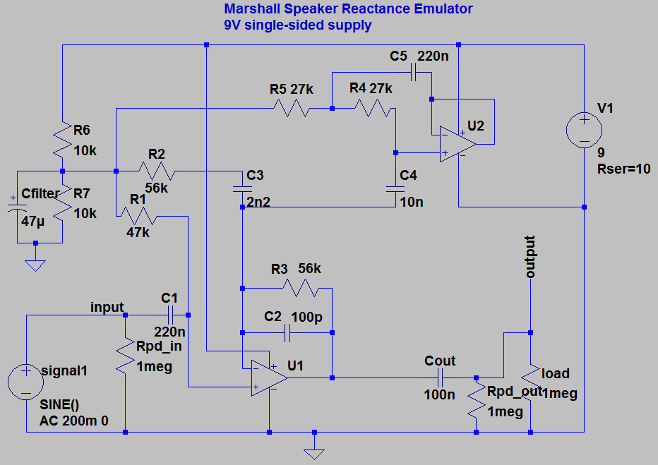
This circuit was adapted from the patent document and the SE100 schematic with minor modifications. The Marshall schematic is based on bipolar power, so I adjusted it for unipolar power: added output cap, and low-noise Vref for mid-rail biasing.
The circuit is designed to make solid state amplifiers sound more like tube amplifiers by replicating the EQ caused by the interaction between the output transformer of a tube amp and the impedance of the speaker. It is especially useful for re-amping a tube amp through a solid state power amp, or adding to a DIY solid state amp. It is not a cabinet simulator, so if you want to record from a non-cabsimmed line output, or plug into a PA, you will probably want a separate cabinet simulator. Most modern, commercial solid state amplifiers already have a similar circuit built-in, so don't expect it to turn your Gorilla into a Bassman. It's also fairly useless in before distortion.
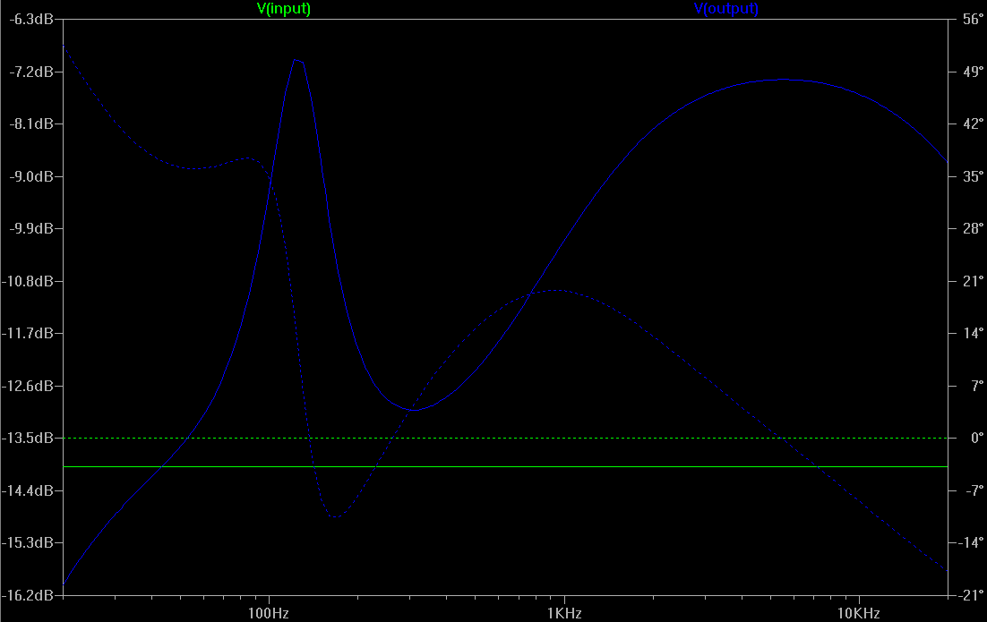
I use it because I feed my Vox AC4TV into a resistive dummy load, tap it for line level, and send it to an LM386-based power amp (her name is Grace, in case you're wondering about the reference on the layout). Adding this circuit to the input of the power amp improves the tone noticeably, but it is not a drastic 'effect'. It's more of a sweetener. It's the permanent input stage to Grace. I originally intended to put a bypass switch on it, but when I tried it on the breadboard, I never wanted to turn it off, so I didn't bother. It's unity gain, plus a narrow boost around 125 Hz and a broad boost in the highs and upper mids. I find it fairly unhearable in front of distortion. It's most useful as a final fixed EQ stage before the power amp, which I avoid distorting.
I played with it quite a bit on the breadboard and found no real benefit from adding any controls or changing any values, but you could add a volume pot on the input or output if you want to. I was happy with a 56k fixed resistor, though I ended up with a 68k resistor because I don't have any 56k SMD's and the difference is not noticeable.
I had a fairly long discussion with someone about it on FSB, in case you want to read more.
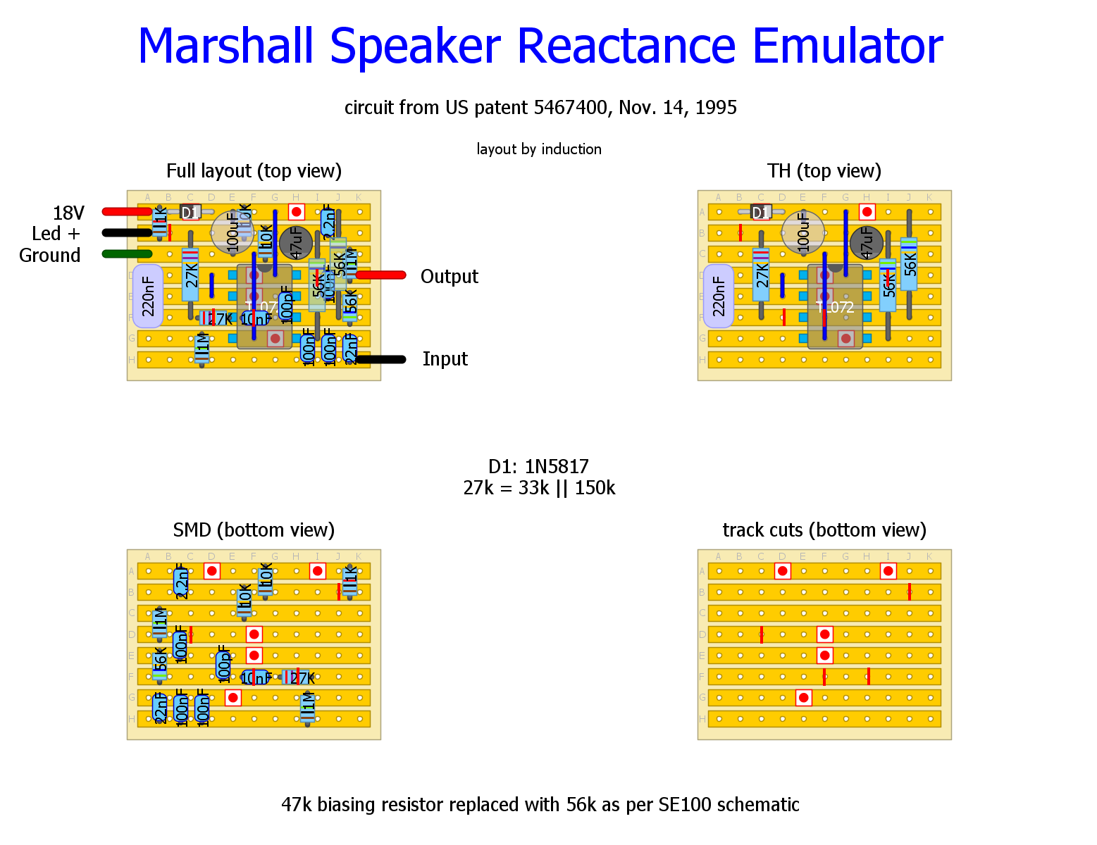
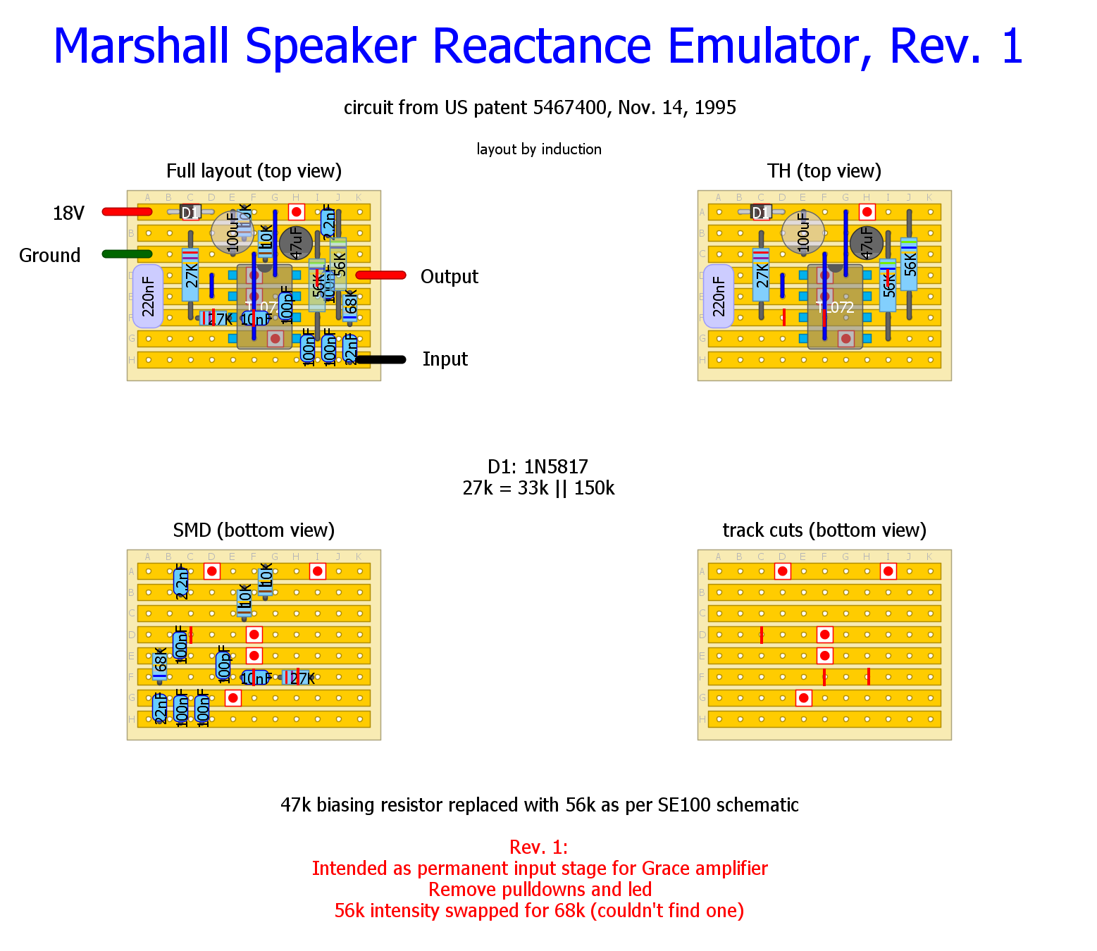
Two layouts here: one designed for how I use it (neither switchable nor adjustable), another for a stand-alone pedal with an intensity control and pulldown resistors, though I can't imagine anyone wanting to use this thing as a pedal.
Verified by me.
Pedal-version:
Version I built into my amplifier:
Schematic:
Frequency response (Input - green, Output - blue, amplitude - solid, phase - dotted):
URL: http://guitar-fx-layouts.238.s1.nabble.com/Marshall-Speaker-Reactance-Emulator-tp31283.html
This circuit was adapted from the patent document and the SE100 schematic with minor modifications. The Marshall schematic is based on bipolar power, so I adjusted it for unipolar power: added output cap, and low-noise Vref for mid-rail biasing.
The circuit is designed to make solid state amplifiers sound more like tube amplifiers by replicating the EQ caused by the interaction between the output transformer of a tube amp and the impedance of the speaker. It is especially useful for re-amping a tube amp through a solid state power amp, or adding to a DIY solid state amp. It is not a cabinet simulator, so if you want to record from a non-cabsimmed line output, or plug into a PA, you will probably want a separate cabinet simulator. Most modern, commercial solid state amplifiers already have a similar circuit built-in, so don't expect it to turn your Gorilla into a Bassman. It's also fairly useless in before distortion.
I use it because I feed my Vox AC4TV into a resistive dummy load, tap it for line level, and send it to an LM386-based power amp (her name is Grace, in case you're wondering about the reference on the layout). Adding this circuit to the input of the power amp improves the tone noticeably, but it is not a drastic 'effect'. It's more of a sweetener. It's the permanent input stage to Grace. I originally intended to put a bypass switch on it, but when I tried it on the breadboard, I never wanted to turn it off, so I didn't bother. It's unity gain, plus a narrow boost around 125 Hz and a broad boost in the highs and upper mids. I find it fairly unhearable in front of distortion. It's most useful as a final fixed EQ stage before the power amp, which I avoid distorting.
I played with it quite a bit on the breadboard and found no real benefit from adding any controls or changing any values, but you could add a volume pot on the input or output if you want to. I was happy with a 56k fixed resistor, though I ended up with a 68k resistor because I don't have any 56k SMD's and the difference is not noticeable.
I had a fairly long discussion with someone about it on FSB, in case you want to read more.
Two layouts here: one designed for how I use it (neither switchable nor adjustable), another for a stand-alone pedal with an intensity control and pulldown resistors, though I can't imagine anyone wanting to use this thing as a pedal.
Verified by me.
Pedal-version:
Version I built into my amplifier:
Schematic:
Frequency response (Input - green, Output - blue, amplitude - solid, phase - dotted):
| Free forum by Nabble | Edit this page |