5 Knob Compressor Help

classic Classic list List threaded Threaded
18 messages Options
Reply | Threaded
Open this post in threaded view
|

5 Knob Compressor Help

Pgorey
I recently built the Ross Comp w Keely Mods and Blend V2 layout and don't have output when the effect is on.  Bypass and LED work.  I have attached a photo of the original layout, my build top and bottom and a redlined stripboard layout to show where audio is heard when probing.  

Original Layout Followed

Top

Bottom

The reason you see jumper wires both top and bottom was to make the double jumps easier to manage.

Where audio is present with the probe.

Pin 2 audio on IC 2 is very faint compared to at the input.

Also, it's not shown but i have audio on all three pins of the trim pot. The trim pot is marked 306 E 202 M.  I am going to socket the trim pot and measure it when I pull it off but it's an old one I had in stock and though I measured its' resistance, I don't think I ever looked up the pinout of it and I may have been on the wrong decimal measurement on my multi meter.

Voltage Readings:

Battery Voltage when plugged in:  9.16

IC 1
1. 0
2.  0.1
3. .01
4. 0
5. .14
6. .11
7. 8.93
8.  0

IC 2
1. 1.28
2. .11
3. .67
4. 0
5.  .67
6. .33
7. 1.26
8.  8.96

Middle-Left Q (near trimmer):
E .39
B 0
C 1.05

Lower-Left Q:
E 7.59
C .54
B 8.92

Lower middle-left Q:
E 0
C 0
B .54

Lower middle-right Q (below 150k resistor):
E 0
C 0
B .54

Lower Right Q:
E .64
C .11
B 1.05


MAO
Reply | Threaded
Open this post in threaded view
|

Re: 5 Knob Compressor Help

MAO
Well done with all the info and pics!

Voltages look suspect. Let's start there.

IC2 Pins 3 and 5 should be about 1/2 pin 8. (4.5v)

With no power applied, blend control set at noon, remove IC2 and measure at the sockets from pin 3 to pin 4 and then from pin 3 to pin 8. Both should read 100k. If not, disconnect lug 2 of the blend control and measure again.

Report back


1978 Gibson Les Paul Standard, Cherry Sunburst
Reply | Threaded
Open this post in threaded view
|

Re: 5 Knob Compressor Help

Pgorey
MAO wrote
Well done with all the info and pics!

Voltages look suspect. Let's start there.

IC2 Pins 3 and 5 should be about 1/2 pin 8. (4.5v)

With no power applied, blend control set at noon, remove IC2 and measure at the sockets from pin 3 to pin 4 and then from pin 3 to pin 8. Both should read 100k. If not, disconnect lug 2 of the blend control and measure again.

Report back
 Right on thank you for the quick response!  I had a feeling that those voltages were no good. Will report back later this evening after work.  Thanks again!  Very hopeful to get this one working!
Reply | Threaded
Open this post in threaded view
|

Re: 5 Knob Compressor Help

Pgorey
In reply to this post by MAO
MAO wrote
Well done with all the info and pics!

Voltages look suspect. Let's start there.

IC2 Pins 3 and 5 should be about 1/2 pin 8. (4.5v)

With no power applied, blend control set at noon, remove IC2 and measure at the sockets from pin 3 to pin 4 and then from pin 3 to pin 8. Both should read 100k. If not, disconnect lug 2 of the blend control and measure again.

Report back
Ok, I have an open circuit between both pins 3+4 as well as 3+8 with power off and both with and without the 2nd lug of the blend knob.

The ICs should be facing with pin one in the top left of each right?  
MAO
Reply | Threaded
Open this post in threaded view
|

Re: 5 Knob Compressor Help

MAO
The ics look correct in the pictures you posted. Top left is pin 1, top right is pin 8. And the dot should be facing the top.

Strange that both readings would be open. Are you sure the meter was set to read 100k?
 
With IC2 still removed, measure across the 100k resister immediately to the left of IC2. See if you get 100k. If so, do the same for the 100k next to the 1n5817.

If both those checks work out, then something is up with the jumpers under IC2.

But double check your meter settings and redo the 1st check before moving on.
1978 Gibson Les Paul Standard, Cherry Sunburst
Reply | Threaded
Open this post in threaded view
|

Re: 5 Knob Compressor Help

Pgorey
Thanks for your continued help!  
I got a chance to take measurements again.  
No power connected.  Took some photos of my measurements which also show the settings on the multimeter.  I started 2nd guessing the MM settings as well when I tested the 100k resistor near IC 2 and also got open circuit but then tested a known value resistor standalone - a 33k which was shown accurately.  I reviewed the cuts and jumpers layout again tonight and compared to my build but must have missed something in the jumper area around IC2 as you mentioned.  I'll have another close look around there tomorrow morning before work.  For now, sleep!


Test Known 33k resistor:


MAO
Reply | Threaded
Open this post in threaded view
|

Re: 5 Knob Compressor Help

MAO
Hang in there, we will figure it out.

Your pictures really help.

I think those tan colored resisters are actually 1M, not 100k. The color bands look like brown, black, green which i believe are 1M.

Set your meter for 2000k ohms and measure them again.
1978 Gibson Les Paul Standard, Cherry Sunburst
Reply | Threaded
Open this post in threaded view
|

Re: 5 Knob Compressor Help

Pgorey
MAO wrote
Hang in there, we will figure it out.

Your pictures really help.

I think those tan colored resisters are actually 1M, not 100k. The color bands look like brown, black, green which i believe are 1M.

Set your meter for 2000k ohms and measure them again.
You are correct.  Totally messed both those 100k resistors up!  Removing now and searching my bin for proper 100k resistors.
Reply | Threaded
Open this post in threaded view
|

Re: 5 Knob Compressor Help

Pgorey
ok, i replaced all the 100k resistors as I had installed 1m in each of the 4 locations.  Measured them this time before installing.  Re-cut after the new soldering and desoldering and brushed off the board before measuring.  Without IC both with and without lug 2 of the blend pot soldered, I'm getting 63.5k at the two resistors you noted as well as between sockets 3+4 as well as 3+8 on IC 2.  
Reply | Threaded
Open this post in threaded view
|

Re: 5 Knob Compressor Help

Pgorey
Ok, I decided to reinstall IC 2 and take measurements again with power.  
IC 1 still looking bad regarding power.  

Battery Voltage: 9.08

IC 1:
1.  0
2. .04
3. .04
4.  0
5. .14
6.  .11
7.  8.88
8.  0

IC 2 Looking better but still not right given your previous voltage note.
1.  4.49
2.  .11
3.  .77
4.  0
5.  .77
6.  .36
7.  4.5
8.  8.87
MAO
Reply | Threaded
Open this post in threaded view
|

Re: 5 Knob Compressor Help

MAO
Some progress, voltage at IC2 pins 1 and 7 now look good, but 2,3,5,6 no good.

When you measured resistance across pins 3-4 and then 3-8 did the resistance climb up to 63k or was it steady?


1978 Gibson Les Paul Standard, Cherry Sunburst
Reply | Threaded
Open this post in threaded view
|

Re: 5 Knob Compressor Help

Pgorey
In reply to this post by Pgorey
It's almost like IC 2 needs to be flipped around so that the current voltages in pins 1 and 7 would switch to pins 3 and 5?  

Is the short, single-line jumper noted on the jumpers/cuts between the farthest right transistor and 10nF cap required?  It's not shown on the component layout page so I'm curious if that jumper is an issue.  I also reviewed diode, transistor, and cap directions/layout and they all appear to be correct.  Checked my jumps and cuts again.  I will check for solder bridges and cold joints in the morning so I can step away from it for a bit and have fresh eyes.  
MAO
Reply | Threaded
Open this post in threaded view
|

Re: 5 Knob Compressor Help

MAO
Yes, that jumper is required.

Thats funny about flipping the ic around, that would line up those voltages but unless that ic is marked incorrectly with the dot, it will probably get damaged if reversed...i wouldnt do it...at least not yet :0)

Quick check, remove IC2, apply 9v power and measure voltage from pin 3 to pin 4, then from pin 5 to pin 4. See if you get 4.5v with the IC removed.

If not, then measure from pin 3 to ground and pin 5 to ground. If you then get 4.5v, most likely pin 4 is not connected to ground as it should.

1978 Gibson Les Paul Standard, Cherry Sunburst
Reply | Threaded
Open this post in threaded view
|

Re: 5 Knob Compressor Help

Pgorey
Thank you!!!  
MAO wrote
Yes, that jumper is required.

Thats funny about flipping the ic around, that would line up those voltages but unless that ic is marked incorrectly with the dot, it will probably get damaged if reversed...i wouldnt do it...at least not yet :0)

Quick check, remove IC2, apply 9v power and measure voltage from pin 3 to pin 4, then from pin 5 to pin 4. See if you get 4.5v with the IC removed.

If not, then measure from pin 3 to ground and pin 5 to ground. If you then get 4.5v, most likely pin 4 is not connected to ground as it should.
Power on, IC 2 removed:

Pin 3 to 4:  .13v
Pin 5 to 4:  .13v

Pin 3 to ground:  .13v
Pin 5 to ground:  .13v

I'm going to go over the layout again and make sure everything is placed right - cuts and jumpers all in the right spot.  Can't hurt to go over it again.


MAO
Reply | Threaded
Open this post in threaded view
|

Re: 5 Knob Compressor Help

MAO
In reply to this post by Pgorey
Strange readings for sure. With IC2 removed, you should have 4.5v sitting at pins 3 and 5, commonly referred to as Vb. Which is generated by those 2 100k resistors and the 22uf cap.

The only components in this circuit that are connected to Vb are pins 3 and 5 of IC2 and lug 2 of the Blend pot. Nothing else.(plus those 100k resistors and 22uf cap which create the Vb)

That should make it relatively easy to track down the fault. Most likely some issue within rows 2 thru 10.

So spend some time checking links, cuts and component placement and values on the top 10 rows.

1978 Gibson Les Paul Standard, Cherry Sunburst
Reply | Threaded
Open this post in threaded view
|

Re: 5 Knob Compressor Help

Pgorey
Had to step away from this one for a bit as I was helping my mom move and work has been crazy busy.  So I reflowed a few spots just to get rid of excess solder, re-cut the whole board and went over the layout again.  I’m going to verify the value of every component again tonight.  I am getting the same reading I had at pin 5 as on the positive side of the 22uf cap.   Removed the cap and the same reading is at pin 5 of IC 2.  All readings with IC 2 removed.  There has to be a solder bridge or misplaced component right?   Could the cap be bad from previously having the wrong value resistors (1m instead of 100k)  All that said, I’m having a hard time understanding how the Vb works as I follow the 9v input on the layout.  There is a cut after the 1st diode so I started following after the diode and am not sure if I should have 9v the entire way or Vb after a certain point and then should stay Vb.  What is really hard for me to see is how only a few components touch Vb despite power having a fairly long path through the circuit if I am following right.  Thanks again for your help!  
MAO
Reply | Threaded
Open this post in threaded view
|

Re: 5 Knob Compressor Help

MAO
Hope that went well.

The cap wouldn't be damaged due to those incorrect resistor values. It could be damaged though if it had been installed reversed, otherwise probably ok.

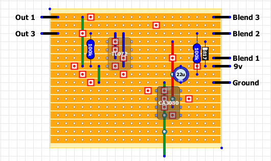
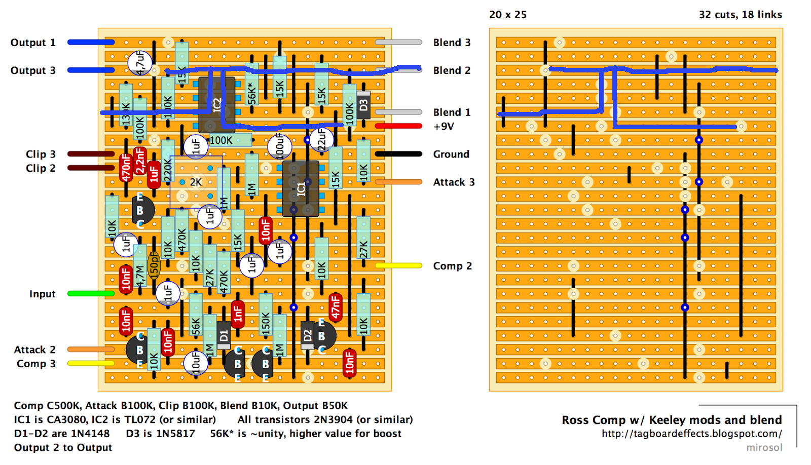
Let's trace the Vb: (remove IC 2)
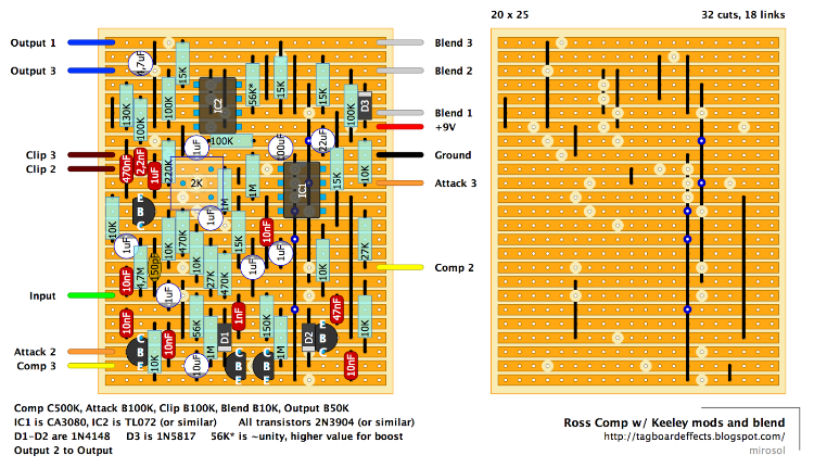
The 9v supply passes through D3 then travels left 4 columns and touches the top of that link and also continues to pin 8 of IC2. It travels down that previous link and splits off to the right at row 8 (double link)and travels to the bottom of the 100k and top of the 10k (should still read about 9v at that junction). It then travels up through the 100k and heads left on row 3, touches the top of 2 links and continues to the top of the 100k at column 5. (This is the Vb rail, should read 4.5v here) The bottom of that 100k in column 5 is connected to ground.

Now back to the 2 links that run under IC2, the Vb travels down those 2 links to pins 3 and 5, and from pin 5 it then travels to the right to the top of the 22uf cap. The bottom of the cap is connected to ground. (Check the cut between the top of the 22u and bottom of D3, also check the cut at IC2 pin 4)

So what's going on is those 2 100k resistors are setup as a voltage divider and split the 9v in half. You'll notice one of them touches the 9v rail, and the other one touches ground. Where the 2 meet is where the voltage is divided, and since they are both The same resistance value (100k), the 9v supply voltage is divided in half (4.5v).  The 22uf cap filters additional noise from the 4.5v rail.

So it appears something is shorting out the 4.5v rail.

You can/should keep IC2 removed while you take voltage checks and try to find the fault. Once you do find the fault and get the 4.5v reading at pin 3 and again at pin 5, then reinstall IC2 and be sure you still see the 4.5v.

Mike
1978 Gibson Les Paul Standard, Cherry Sunburst
MAO
Reply | Threaded
Open this post in threaded view
|

Re: 5 Knob Compressor Help

MAO
Here's a simplified view:Check component values and placement.

Red links =9v, Blue links =4.5v, Green links = ground.


And here is the entire Vb trace. Check everything and anything that could be shorting to the blue trace line.


1978 Gibson Les Paul Standard, Cherry Sunburst