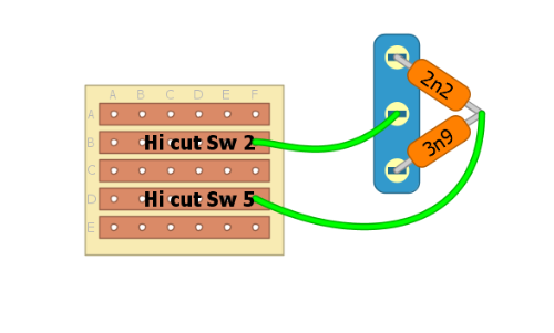
***EDIT*** Sorry, didn't notice that the switches are on/off/on. With the solution described below you can only have the On/On function..
Well, it's actually possible for this situation but it's gonna get a bit messy.
I'll explain the "Hi cut switch".
So, using a spdt, the left column of the switch stays as is with the difference that both caps are: Left side soldered to the switch, right side both connected to "Hi cut sw 5" on the board. That way your signal travels through one of the caps for each switch position and back to the board as it is supposed to.
The same goes for the clipping switch, you choose with the spdt at witch diode network the signal will flow throuh and both networks' end leads directly to "gain 1", where pin5 of the dpdt would be connected.
Ah, better draw it. Here.

Hope that helps!
