Chris60601 wrote
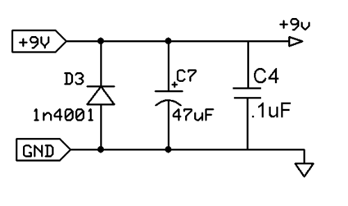
I get the diode (for polarity protection) but I dont understand the usage of the resistor.
It's easy to think of the cap to ground as a 'filter cap' and believe that it shunts any noise on the power line to ground, but it's not quite true. In fact, the cap is the bottom half of a
low-pass filter that uses the power supply as the input signal. The corner frequency of this filter is 1/(2*pi*RC).
Without any resistance, R becomes zero, and the corner frequency of the filter becomes infinite, ie. the filter does nothing. In practice, without the resistor, the low-pass filter relies on the resistance of the copper, the output impedance of the power supply, and/or the ESR of the cap to fill in the R in the formula. If all of these are small, then the filter won't work so well because the corner frequency will be too high.
Adding a small value resistor in series between the power supply and the rail used by the circuit gives you a predictable resistance for the power filter to work. Upside: the larger the resistor, the lower the corner frequency for a given cap value. Downside: the larger the resistor, the lower the supply voltage to the circuit. It's a balancing act, choose a resistor large enough that you can get decent filtering with a reasonably small cap, and small enough that you don't drop your supply voltage too much. The supply voltage requirements of all circuits are not the same, neither are the supply filtering needs of different circuits and supplies. In some circuits you can get away with 100R, in others even 10R is too much. This is why there is no single, correct supply filter that works on all circuits. They have to be chosen to fit the circuit in question.
The second small cap is added because many electrolytic caps have a capacitance that is dependent on frequency. So a large electro might be chosen to pass all frequencies above some threshold, but in practice it inhibits higher frequencies more than you'd expect, which means the very high frequencies won't be filtered out so well and the circuit may be susceptible to RF oscillation, which you can't hear directly, but which does often have a very audible effect on the signal. So you use a smaller value cap in parallel to help the filter at the frequencies where the electro is not as effective. This works best if the smaller cap is film or ceramic, because that takes advantage of the different frequency-dependent capacitance of the different materials. If you use a small electro in parallel with a big one, you are just effectively increasing the value of the bigger cap.