Advice : Add a 47r resistor on every +9v rail!

12

12

Administrator
|
Hi mates!
Just to comment on it. No matter how great you PS is, and how clean and good is your home's grounding, you'll always build an effect deadly silent when powered by battery, but noisy as hell as soon as you plug it to your power supply. I''m not sure about the reason why it happens, but in some effects, like the Foxx Tone Machine, the Hummingbird, the Boss CE-2 or the Sonic Titan, to name a few that I've built many times with the same result, you'll get an unbearable white noise when you plug them to the wall. If that happens to you too, the solution is easy: solder a 47r-100r resistor on the +9v path before the current hits any component. It seems incredible, but the little filter that this tiny resistor creates, cleans 99% of the white noise. If the pedal is not a fuzz and you solder a bigger filtering cap, it gets deadly silent. Give it a try, and you'll see it by yourself. BR |
|
|
This is a good idea most of the time, but you have to be careful with some circuits. The amount of voltage drop across that resistor depends on the circuit. Usually it's fine, but some circuits (Belton brick reverbs, for example) can turn into white noise machines with that resistor. With a fuzz face, that resistor will change the bias on Q2, but you can swap collector resistors to readjust the bias to the sweet spot.
The way it works is the small series resistor followed by the filter cap to ground form a low-pass filter with a very low corner frequency. For example, a 47R series resistor and a 100uF filter cap have a corner frequency of about 34 Hz, which is lower than the 60 Hz hum and all of its harmonics. Anything coming from the PSU that's above 34 Hz gets attenuated to ground. When you can't use the series resistor, the intrinsic resistance of the copper will still create a low pass filter, but it will have a higher corner frequency. You can use a bigger filter cap to compensate. (The corner frequency is inversely proportional to the product of the series resistance and the parallel capacitance.) The worst hum happens with circuits that have a resistive link between V++ and the input to a gain stage, for instance when you make a voltage divider with two 1M resistors to bias the input of an op-amp, the base of a bjt, or the gate of a jfet at Vref. The power noise rejection of op-amps is pretty good, but when you feed PSU hum to the input, it gets amplified along with the signal. This is what noiseless biasing is for. Instead of linking the signal directly to the Vref voltage divider, you make the voltage divider out of two 10k resistors and link it to the signal with a 470k resistor. Then you add a filter cap to the Vref junction and you get pretty good hum reduction. (Without that extra 470k resistor your high end will bleed to ground through the filter cap. The 470k is chosen because it's roughly the same impedance as the parallel 1M resistors.) This also reduces thermal noise because the voltage gradient occurs across the smaller 10k resistors instead of the big 1M resistors. Some circuits (Fuzz face, Cot-50, etc) have screwy biasing schemes that don't allow for noiseless biasing. I've found that no amount of power supply filtering can fix a noisy (ie unregulated) PSU in these circuits. This is why I only use regulated adapters on my pedals. The regulator kills that hum like magic. My fuzz face and Cot-50 are noisy as a waterfall with unregulated adapters, and dead silent with regulated adapters. And it is very easy to convert a 12V unregulated adapter into a regulated 9V silent adapter. I still include as much filtering as I can on my builds anyway, just to be sure. |
|
Administrator
|
Great answer!
Thank you very much, I'll keep this info in mind for sure! Luckily, I decided time ago that circuits like fuzz face, Zonks, MK1, and so on (mainly old school effects) will only be powered by battery on my builds. BR |
Re: Advice : Add a 47r resistor on every +9v rail!
|
|
In reply to this post by induction
How is this done? Are there instructions you can point me to? Thanks
Keith
|
|
|
A voltage regulator is one of the simplest circuits you can make.
Here's the 78L09 datasheet application circuit with just three components: 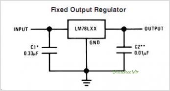 You'll find different suggested values for C1 and C2, depending where you look. I usually put a 100uF and a 100nF in parallel on the input side, and a 22uF and a 100nF in parallel on the output side. (Probably overkill, but so be it.) Tantalums are good here as long as the voltage rating is high enough and you watch the polarity. You can also add polarity protection (1N4001 in series with the 12V input). You don't need a series resistor in front of the caps, but if you decide to use one make sure it can handle the power or it will burn up. You can put several of these in one box and make your own multi-PSU. I made two of them and power them with laptop PSU's, which are switching supplies and thus usually too noisy for audio use. After going through the regulator, they are quiet and clean. A few things to keep in mind. 1. Current: 7809 are quoted at 1A or 1.5A. 78L09 are quoted at 100mA or 150mA. One 78L09 regulator can power 10 or so dirt pedals on a daisy chain. Delays and reverbs can be more power hungry, but one delay and 3 dirt pedals is probably fine. Obviously, your 12V supply must be able to supply that much current. If you feed a bunch of regulators with one +12V supply, then any series diode that you use for polarity protection must be able to handle all of the current you use. You can use parallel diodes if necessary. 2. Heat: 7809's should be heat-sinked. (78L09's don't need heat-sinks.) The amount of heat generated correlates with supply voltage and with current consumption. (You can feed them +18V as input instead of +12V, but they'll get a little hotter.) You can get proper heat sinks that fit on them, or bolt them to the enclosure (the tab is continuous with the ground pin). I just use a couple of washers. Whatever you use, thermal compound is important. 3. If the output voltage goes higher than the input voltage, reverse currents can let the magic smoke out of the regulator. That's why the caps on the input size are larger than the caps on the output side. (If you pull the plug, the input side will discharge slower than the output side, thus preventing reverse currents.) You can also put a diode across the regulator with the cathode on the input pin and the anode on the output pin. This protects the regulator if you accidentally ground the input. I don't use the diode, but on my multi-PSU's I use standard 2.1mm center negative plugs on the output side, and a much smaller plug on the input side so I don't accidentally reverse the input and output and let the smoke out. To regulate a single unit, it might be best to make all of the wiring permanent. Then you don't have to worry about it. 4. Vero can only take so much current, so consider each current pathway when wiring up a multi-PSU. 5. The pinouts of 7809 and 78L09 are reversed. If you have a layout for one and you want to use the other, just rotate it 180 degrees. Here are some vero layouts for the two that I made. (Again, total overkill, but I don't mass produce stuff, so I can get away with it.) Both incorporate a 7660S charge pump (max output current: 45mA). The yellow caps are tantalum, but electrolytics are fine too. The 100nF's and the led clr are SMD (size 1206). I didn't include the polarity protection diodes when I built them. If you don't like SMD, or you don't want the charge pumps, or you want to change anything, you can just use these layouts to get ideas for making your own. 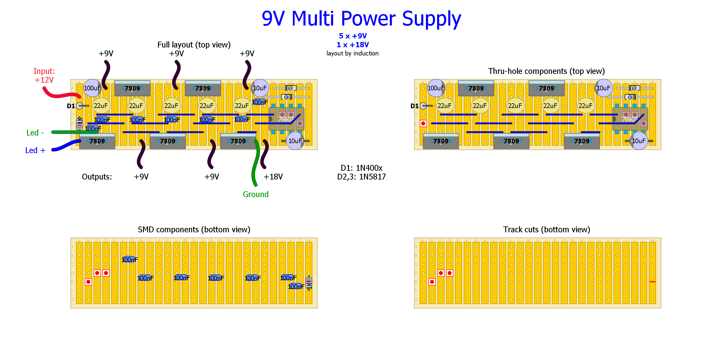 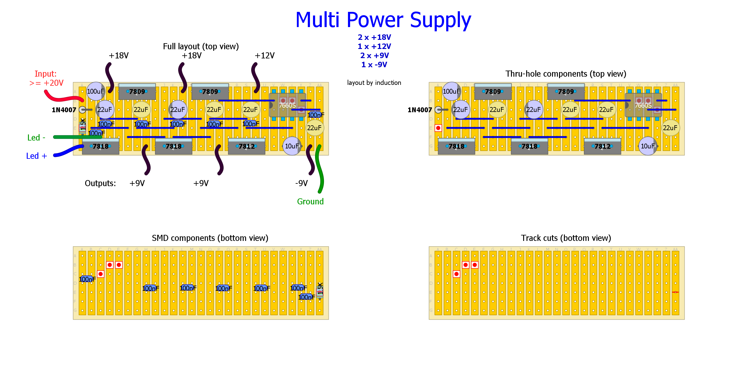 Hope this helps. |
|
|
Great , I've been thinking about building a power supply , seeing I"ve built more pedals than I can power effectively . One question , do all 9v points grounds link to the 1 ground point on the vero ?
|
|
|
Can You please tell me what is D1 polarty on vero above? When You said that 1 78L09 can power 10 pedals, is that it can power it by daisy chain from one output of this power supply or what?
Please can you also explain how can all be smoked? I don't get that part. Thanks. |
|
|
In reply to this post by crw414
Yes they do. Here's a couple of pictures that might be helpful.
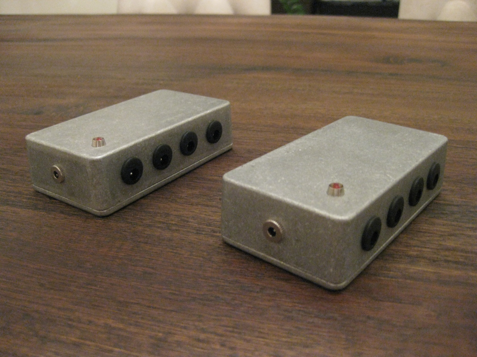 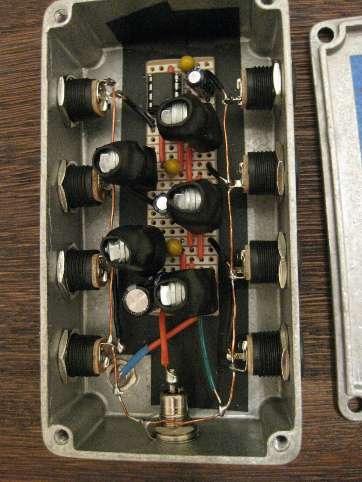 You can see in the gutshot, that I run a single ground bus to all of the jacks and the led cathode, so there's only one ground connection to the board. (It's actually located at the point marked 'Led -', not the point marked 'Ground'. But you can put it wherever is most convenient.) You can also see from the external shot, that it is going to be difficult or impossible to accidentally reverse the input and output voltages because the input voltage jack is a different size than the output jacks, and the none of the plugs will physically fit in the wrong jack. I recommend this trick because reversing input and output can let the magic smoke out of the regulators. The input voltage jack is also center positive. This is necessary because the jack is not isolated, and the sleeve electrically connects to the enclosure. You don't want DC on the enclosure. It's probably not dangerous at 12 or 24 volts, but it's just a bad idea. Grounding the input voltage of a charged regulator will let the smoke out unless you include a protection diode on each regulator, which I didn't. The way it's wired, that's nearly impossible, but if you have your input voltage sitting on the enclosure and you ground the enclosure (by touching it to another pedal, for instance) it's pretty likely. Then you'll have to replace all of your regulators. Finally, notice that each regulator has a heat sink made of three small washers. The washer size was selected for maximum contact with the regulator tab, and there is thermal compound at each mating surface. The tab of each regulator is shorted to the ground leg, so I heat-shrinked each of the regulators as a precaution against accidental shorts. |
|
|
Thanks induction that's very helpful , when I can I'll sit down and plan my power supply
|
|
|
Can You please answer on my question? What is orientation of D1? Also can this be done with plastic enclosure? Also what do you mean by grounding input regulator? You say that input must not be grounded but it is grounded on pictures. Can You please explain this more detailed?
Thanks. |
|
|
Hi Larry. Sorry I missed your post.
1. D1 is a series polarity protection diode, so the anode goes to the input voltage and the cathode (stripe side) goes toward the first regulator. Think of the diode like an arrow with the head on the stripe side. The arrow points to the right on the layout. As mentioned above, I replaced this diode with a jumper on my builds because the diode limits your total combined current to 1A. 2. Yes, a plastic enclosure is fine. 3. Sorry for the confusion about grounding the input, my phrasing was unclear. The power supply has one input and several outputs, all of which need one lead tied to ground. Additionally, each regulator has a input pin, an output pin, and a ground pin. If the input pin on any regulator is tied to a lower voltage than the output, current will flow backwards through the regulator, and it will die. (The problem only occurs if the input pin is tied to a lower voltage than the output pin. If the input pin is floating, everything should be okay.) This means that it is important not to accidentally reverse your input and output cables, or to accidentally plug an adapter into one of the outputs while there is a lower voltage adapter plugged into the input, because under certain conditions one or all of the regulators will be destroyed. You can protect the regulators against reverse currents by putting a diode between the input and output pins of each regulator (arrow pointing from output pin to input pin). I didn't do that in this layout because I use different size plugs on my input and output cables which will not physically fit in the wrong jack, and because I make them for my own personal use. If I was to sell them, I would protect them against all the possible ways things could go wrong, making them more bulletproof, but more expensive as well. 4. Each regulator can pass up to 1A (or 1.5A depending on which datasheet you believe) of current. The amount of current consumed by a pedal depends on the circuit. The average distortion circuit uses maybe 10mA, and anywhere from 1mA to 20mA for the led, depending on the type, the color and the limiting resistor. (The circuits consume slightly more current when engaged, but still consume current when disengaged, except for the led.) So you can daisy chain something like 30 distortion pedals to be used simultaneously (or up to about 100 of them, if you only use one at a time) from a single regulator. Other circuits, especially delays and reverbs, use a lot more current (a belton reverb brick uses 60-100mA by itself, plus the op-amps and led, which is why it's not a good idea to try to use them with batteries). In any case, if you use a 1N4001 for D1, you are limiting the entire power supply to 1A for all the regulators combined. If you replace it with a jumper or a more robust diode, you can supply much more current. In principle, you can get 1A or more from each regulator. In practice, I would expect that almost nobody uses more than 1A for even a large pedal board full of homemade stompboxes. Vero can only handle so much current before it burns, and most adapters are limited to less than 1A, though laptop supplies can often go higher. So the question of how many pedals can be powered by one or all of the regulators depends on several factors, and varies from person to person. In general, digital circuits use much more current. They also tend to introduce lots of noise into the power supply, which leaks into the other circuits, so it's not good to daisy chain them with other pedals. I would not plug any digital circuits into the above layout except for PT2399 delays or belton reverbs (these are technically digital but don't have all the extra digital control circuitry in them, so they don't add much noise to the PSU, though they do consume more current than dirt pedals), so the layout will power far more pedals than I will ever use, even with a 1A limit on the supply. The main reason I included so many regulators in the layout is to allow me to spread the current out over different pathways, which keeps the heat generated by any individual regulator to a minimum. |
|
|
This post was updated on .
Best answer so far here on this site. Thank You very much. This is very helpful.
Can You please confirm my plan for building this so I can be sure it will work? This is my plan: 1. Put it in plastic box. 2. Ground as you show it on your pics. 3. Use 1n4001 for D1 4. Use one daisy chain from one output to power 5 pedals (dirt, analog delay, chorus, boost, tuner) 5. Use others to power other pedals 6. I will use metal jack for input and plastic for output (with out protection diodes or I will solder them from output lug to input lug of each regulator) 7. I will use 78L09 x 5. Also I would add that this is one of best projects on this forum because it is something we all need and will need more than one. Do You have any other projects? Great work! P.S. How can I make it smaller and cut out 18v output part? Can you make one without it or just tell me what to delete...I'm building first one...thanx :-) |
|
|
All of your numbered items will be fine. I will address a couple of issues just for clarity.
3/4. Choruses and analog delays are a little more power hungry than other pedals. It should be fine to put them both on the same regulator, but it wouldn't be a bad idea to use two 1N4001's in parallel to allow for more current. It shouldn't be necessary, but it might save you some trouble down the line. 6. If you use a plastic enclosure, you don't have to worry about which tab touches the enclosure, so you can use metal or plastic for any of the jacks. My input jack is metal only because I wanted a size that couldn't be confused for the standard 2.1 mm and the only appropriate jack I could find at my local surplus electronics store happened to be metal. Because it was metal, I had to reverse the polarity (center positive instead of center negative) to avoid DC on the enclosure. With a plastic enclosure, this is not a problem. You can essentially do whatever you like with the jacks without fear of shorting. So, shorter answer, yes that will work, but you have other options if you prefer. Just make sure you make a note of how you wired it. I wrote the details on a piece of painters tape and put it on the inside of the lid. The charge pump for +18V or -9V can be removed without affecting the rest of the circuit. Just remove everything to the right of the last regulator. You'll have to take your ground wire from somewhere else on the vero. I used the spot marked 'Led -' for my ground connection and wired the led cathode to the ground bus that connects all of the jacks. If you want to see one of my other projects, search for All Star Reverb on this forum or at freestompboxes.org |
|
|
Can I put 4002 instead of two 4001's for more current? Also please can You specify what to remove for more compact layout...I have only 25 row vero..I don't know does that include and 7660 with all caps and jumpers, altough I just wonna narrow it down to 25, so it is no problem to leave 7660 on...please if is not a trouble, a bit more info.
|
|
|
Keep everything up to column T, remove column U and beyond.
As for the diode, all 1N400x diodes are 1 amp maximum. The last number refers to different PIV (peak inverse voltage, ie how much reverse bias can it stand before it begins to conduct current the wrong direction). For more current, you can either add 1N400x's in parallel, or you can switch to 1N540x, which can deliver up to 3A. I haven't used them, but I think the bodies are a little larger, so I'm not sure whether the legs fit in vero holes or not. You may need to enlarge the hole with a small drill bit. The forward voltage drop is also a little larger (it's listed at 1.2V), but I think it should be okay for powering 7809's with a +12V supply. |
|
|
Ok. Thanks. I get it now. :-) Just to be sure - if I put one 4001 it will give 1A to whole box (that means that only 1000mA can be pulled out of all output jacks thogether - no on each one), and if i solder 2x4001 one on each other it will give 2000mA to whole box - right?
|
|
|
You got it.
Edit: To clarify, put the diodes in parallel not in series. |
|
|
This post was updated on .
If I don't want to mess around with smd components, how would the layout look? Also, it looks like you are using tantalums for the 22uFs what would be the pos and neg on them? One more thing, if I am only going to use this for a 9v power supply and remove from U on, could I use a 9v power supply that supplies 2000 milliamps of current?
|
|
|
Just my two cents...
http://www.thomann.de/gb/harley_benton_powerplant_junior.htm For that price, it's a no-brainer. Like a budget Voodoopower. Isolated outs, nice quality and they even give you a bunch of connectors/daisy chains/Y cables! Costs just a fraction more than building your own thing with regulators, but it saves you time and effort! |
|
|
In reply to this post by DannyBoy
If you compare rocket's layout and mine, you'll see your first two questions answered. 1. film caps instead of SMD 2. electro's instead of tantalum (you can still use tantalum if you want, but rocket's layout tells you where to put the negative leg. (The center pin of the regulators is for ground, so that's where you put the negative leg.) For your third question: Rocket's layout has 6 regulators and a charge pump. Decide how many regulators you want and just and just chop off everything to the right of the last regulator on the layout. For example, if you want 5 regulators, cut off everything from U on. If you want six regulators, cut off everything from Y on. You will still need a minimum of +12V supply voltage. Regulators need two or three extra volts above your target voltage to function properly. More supply voltage is ok, but I would include heat sinks on the regulators then. (I actually included them anyway, but it's probably not necessary with a +12V supply and 9V regulators. 2000 mA is probably plenty unless you try to run DSP effects from it. Make sure you read this whole thread before you build either my layout or rocket's. Especially the part about the polarity protection diode and current limits. If you order all your parts (enclosure, components, jacks, plugs, vero) from Mammoth or somewhere comparable, you'll pay about $30 US for everything including daisy chains and shipping. You can do better if you shop around on eBay. I buy all of my stuff from a local surplus shop, so I spent about $10 on each one. The Harley Benton looks like a great deal, and isn't that much more expensive (about $40 US plus shipping) than DIY. It just depends on what you pay for parts, and why you build. I build because it's fun. If I wanted to save money, but didn't enjoy building for its own sake, I would just buy the Harley Benton. If you just want a painting to hang on the wall, the discount shops are full of them and you can get one cheap. But if you want the experience of painting something, the effort is the whole idea. Plus you end up with a painting when you're done. |
«
Return to Open Chat
|
1 view|%1 views
| Free forum by Nabble | Edit this page |