Amp discovery!

classic Classic list List threaded Threaded
195 messages Options
1 ... 5678910
Reply | Threaded
Open this post in threaded view
|

Re: Amp discovery!

Scotchegz
Combo I experimented with : Control plate is stainless salvaged from an old incubator i teared down, Timber  is old bed slats, I also use hessian for grill cloth "comes in nice colours".
Ended up using the Hiwatt stacked Tonemender as preamp and a 10" skytec speaker off ebay.
Cheers for the previous work of others for inspiration and ideas in the forum. My build !

Reply | Threaded
Open this post in threaded view
|

Re: Amp discovery!

Tesla
https://www.ebay.com/itm/IRS2092-CLASS-D-Audio-Receiver-Power-Amplifier-AMP-Kit-200W-MONO-Assembled-Board-/311685758233?_ul=CA

Found this one, do you guys think it will work for what we need. I built a BE100 model using the 60w module and the powersupply Travis linked in a 1590DD which is awesome for sure but I’d like something with more output as well

Time to start reading the data sheet lol
Exodus Effects
Reply | Threaded
Open this post in threaded view
|

Re: Amp discovery!

Tesla
This post was updated on .
Ok so the ad says something about  it needing a +-50V 8a power supply but I’m also reading this else where

If the total system price is an important factor, a simple mains transformer with suitable rated power and output voltages can be used and one high current rectifier bridge only. Since music signal has a high crest factor, and the IRS2092k amplifier modules have very high efficiency, the power rating of the transformer can be lower than the total power of the amplifiers, but at least half the total power of the amplifier modules supplied. For example the minimum rated power of the transformer used to supply two 200W amplifier modules is 200VA. Following mains transformers voltage and current values are suitable: 240VA transformer for two 200W amplifier modules version with 2×32-33V AC, 3.6A
Exodus Effects
Reply | Threaded
Open this post in threaded view
|

Re: Amp discovery!

Tesla
This post was updated on .
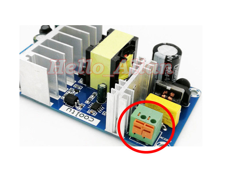
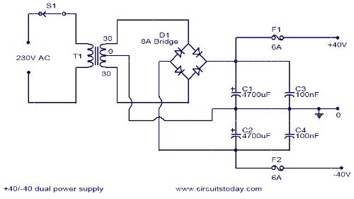
Ok so after some research you can either use the above method or a symmetrical power supply,  does anyone think this will work or am I better just building something else with it.  For $20 I’ll find a use for it for sure but it would be pretty amazing if it worked similar to the other module
These are the Key Parameters for one mono amp.

“Power Efficiency: > 90%
Quiescent Supply Current: 20mA
Freq. Response: 20Hz ~ 20KHz
Rated Output Power: 200W @ 4 Ohm

Voltage Range: DC +/- 30 ~ 60V
Recommended Voltage: DC +/- 50V ~ 3A

Ground on the amp is not the same as ground on the switcher. In the latter case, it is safety ground only. There is no electrical connection between either + or - and ground. However, the ground on the amp is part of the electrical circuit.

Therefore, in order to make a balanced ps out of two switchers, you connect them just as you would with batteries - you connect the + of one with the - of the other. This connection point will then be what you have to connect to the ground of the amplifier. The open plus of one of the switchers will be connected to the + of the amp, the open minus of the other switcher to the - of the amp.”
https://hifimediy.com/power-supplies/SMPS300RE-45V-230V


Needless to say proper fets that can function at a higher voltage then your typical j201/202 would be required or better yet a preamp section consisting of 12ax7’s. I’ve found a bass amplifier that uses the same two IC’s so it can most definitely work and from the video sounds beautiful
Exodus Effects
Reply | Threaded
Open this post in threaded view
|

Re: Amp discovery!

Sensei Tim
hey guys,

do any of you get a loud pop when you turn the power on for the amp & pre-amp circuit?

What would be a good way to help reduce the popping?
Reply | Threaded
Open this post in threaded view
|

Re: Amp discovery!

kuzieem
The popping of power amp is due to "transient state" The only way to avoid loud popping is to delay  the speaker plugging when turning the amp on.
Plug the speaker trough relay-delay
circuit. I'm using this one:


czw., 21.06.2018, 22:15 użytkownik Sensei Tim [via Guitar FX Layouts] <
ml+s42897n43266h60@n6.nabble.com> napisał:

> hey guys,
>
> do any of you get a loud pop when you turn the power on for the amp &
> pre-amp circuit?
>
> What would be a good way to help reduce the popping?
>
> ------------------------------
> If you reply to this email, your message will be added to the discussion
> below:
>
> http://guitar-fx-layouts.42897.x6.nabble.com/Amp-discovery-tp31594p43266.html
> To unsubscribe from Amp discovery!, click here
> <http://guitar-fx-layouts.42897.x6.nabble.com/template/NamlServlet.jtp?macro=unsubscribe_by_code&node=31594&code=cGlvdHJrdXplbWN6YWtAZ21haWwuY29tfDMxNTk0fC02NzI5NTgzMzA=>
> .
> NAML
> <http://guitar-fx-layouts.42897.x6.nabble.com/template/NamlServlet.jtp?macro=macro_viewer&id=instant_html%21nabble%3Aemail.naml&base=nabble.naml.namespaces.BasicNamespace-nabble.view.web.template.NabbleNamespace-nabble.view.web.template.NodeNamespace&breadcrumbs=notify_subscribers%21nabble%3Aemail.naml-instant_emails%21nabble%3Aemail.naml-send_instant_email%21nabble%3Aemail.naml>
>
Reply | Threaded
Open this post in threaded view
|

Re: Amp discovery!

Travis
Administrator
You da man kuzieem!!
Reply | Threaded
Open this post in threaded view
|

Re: Amp discovery!

Scotchegz
In reply to this post by Sensei Tim
I'm pretty sure I heard somewhere, "if you're talking about the 3118" placing a electrolytic cap 5 to 10uf across the mute pads slows the start up and stops popping, The new batch I received last week don't seem to have this problem, they also don't have an on board led.
Reply | Threaded
Open this post in threaded view
|

Re: Amp discovery!

arkham00
In reply to this post by rocket88
Hello everyone,
So I finally built this project but I'm having some trouble.

At first I tried to connect the amp ouside of the enclosure and it worked fine, I had no noise.
Then I put it in a small box I had laying around, I isolated the bottom with some duct tape, drilled some holes but and it only made a high pitched noise.
After some tests I figured out that the problem is with the input jack: if I leave it floating and the rest of the board mounted then it works fine, but if I screw it in its hole I have the noise.
I'm using an open jack for the input and I didn't connect the sleeve to the negative pad as suggested.
The output jack is an isolated type.
What should I do? Order an isolated jack? Connect the sleeeve? What else?

I'll attach a pic to show you the actual thing. 

On a side note, I also tried a 12v laptop supply I have, it has inverted polarity, so I inverted the wires on the power pads on the board, it powered up but I only had some noise and the board started to heat up, so what else should I be looking for for a compatible power supply? 
Maybe it delivered to much amperes? 3 or 4 I think
Or maybe it is safer to stick with a 9v pedal  supply and build a charge pump?

Thank you so much guys

On Wed, Nov 8, 2017, 01:21 rocket88 [via Guitar FX Layouts] <[hidden email]> wrote:
that's similar to what i used. one big think you need to do. make sure the power supply is enclosed. you're going to have a 120VAC coming in and you can easily get a nice shock.

btw, for those that are curious for how these little class d amps sound with a preamp in front. here's a short clip of my build, 100watt mini model t. gain for both channels is at noon, and i through one of my distortions in front of it that's essentially a highly modded Ross Distortion.


If you reply to this email, your message will be added to the discussion below:
http://guitar-fx-layouts.42897.x6.nabble.com/Amp-discovery-tp31594p40457.html
To unsubscribe from Amp discovery!, click here.
NAML

IMG_20180824_091431.jpg (2M) Download Attachment
Reply | Threaded
Open this post in threaded view
|

Re: Amp discovery!

rocket88
Administrator
Without pictures it’s hard to tell what’s the issue. Part of the issue could be that all your grounds are not connected to the chassis. The issue with the power supply your using could be not that it’s power is inverted, but that it’s sending +12V to the chassis rather than ground. As far as the amount of amperage you need take a look at the data sheet for the chip on the amp board to see how much it needs. I don’t remember, but I think it needs 4A, and can say for sure that a charge pump with +9V isn’t enough.
Reply | Threaded
Open this post in threaded view
|

Re: Amp discovery!

arkham00
Hi, thank you for the answer.
There actually is a picture attached to the message, it just doesn't show in the body of the message I don't know why. 
Do you mean that I need to actually solder the ground on the inside of the box? I never did to any of the pedals I built
For the amperes thing, it is actually working with a 9v supply of 1A who also daisy chains 6 more pedals, 4A it seems huge to me, I'm confused
I also believe that someone in here said that all it needs is 120mA
I'm going to look for for the data sheet

On Fri, Aug 24, 2018, 21:32 rocket88 [via Guitar FX Layouts] <[hidden email]> wrote:
Without pictures it’s hard to tell what’s the issue. Part of the issue could be that all your grounds are not connected to the chassis. The issue with the power supply your using could be not that it’s power is inverted, but that it’s sending +12V to the chassis rather than ground. As far as the amount of amperage you need take a look at the data sheet for the chip on the amp board to see how much it needs. I don’t remember, but I think it needs 4A, and can say for sure that a charge pump with +9V isn’t enough.


If you reply to this email, your message will be added to the discussion below:
http://guitar-fx-layouts.42897.x6.nabble.com/Amp-discovery-tp31594p43781.html
To unsubscribe from Amp discovery!, click here.
NAML
Reply | Threaded
Open this post in threaded view
|

Re: Amp discovery!

Sensei Tim
are you using an isolated speaker jack?
Reply | Threaded
Open this post in threaded view
|

Re: Amp discovery!

arkham00
For the input no I'm not, should I? 

On Fri, Aug 24, 2018, 23:43 Sensei Tim [via Guitar FX Layouts] <[hidden email]> wrote:
are you using an isolated speaker jack?


If you reply to this email, your message will be added to the discussion below:
http://guitar-fx-layouts.42897.x6.nabble.com/Amp-discovery-tp31594p43783.html
To unsubscribe from Amp discovery!, click here.
NAML
Reply | Threaded
Open this post in threaded view
|

Re: Amp discovery!

Sensei Tim
for the speaker jack.
Reply | Threaded
Open this post in threaded view
|

Re: Amp discovery!

arkham00


Ok I managed to post the pic, open jack for the input, closed jack for the output
Reply | Threaded
Open this post in threaded view
|

Re: Amp discovery!

spacefuzz74
For the AC-DC converter board, which terminal is for the hot (black wire) and which one is for the neutral (white wire)?  The board isn't labeled (see photo), so maybe it doesn't matter?  Thanks for any help!

Reply | Threaded
Open this post in threaded view
|

Re: Amp discovery!

Blackboarcult
If it's AC, it doesn't matter.
I got a similar one last week which has a hole for a ground bolt but no markings for phase and neutral either:


A lot of these chinese psus and amps seem to have no markings but a careful look just below/behind terminal blocks shows the + and - symbols
Reply | Threaded
Open this post in threaded view
|

Re: Amp discovery!

rocket88
Administrator
Black positive, white neutral always. Even though it’s AC there is a common wiring scheme and you want it the same as the outlet you’re plugging into. Wire the ground from the plug to the ground on the chassis.
Reply | Threaded
Open this post in threaded view
|

Re: Amp discovery!

spacefuzz74
Hey Rocket88,

All of these AC-DC boards do not have labels for the AC in, so I was just curious as to what terminal was what on the board...do you know?
Reply | Threaded
Open this post in threaded view
|

Re: Amp discovery!

rocket88
Administrator
On mine, which are the same as the ones in the pic you posted, neutral is wired to the left hole, positive the the right when looking at the board with the orange tabs facing you.

Remember though to match your power cable when wiring the socket up to the power switch board.
1 ... 5678910